STEERING LOCK SYSTEM Steering Lock does not Lock
DESCRIPTION
The steering lock actuator activates the steering lock motor and moves the lock bar into the steering column to lock the steering.
When the steering lock is operating, the steering may not lock when the lock bar is not aligned with the lock hole of the steering column. In this case, the steering can be locked by turning the steering wheel a little in the same manner as is done for a vehicle with a mechanical key to change the position of the lock hole.
| Problem Symptom | Data List Item | Active Test Item |
|---|---|---|
| Steering Lock does not Lock |
Entry&Start |
- |
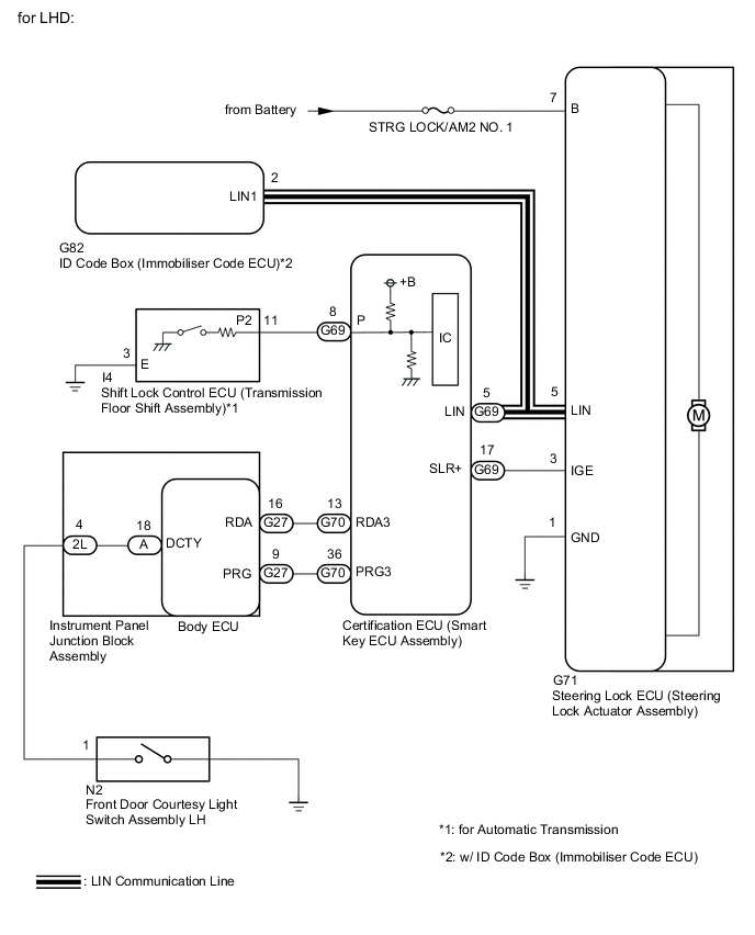
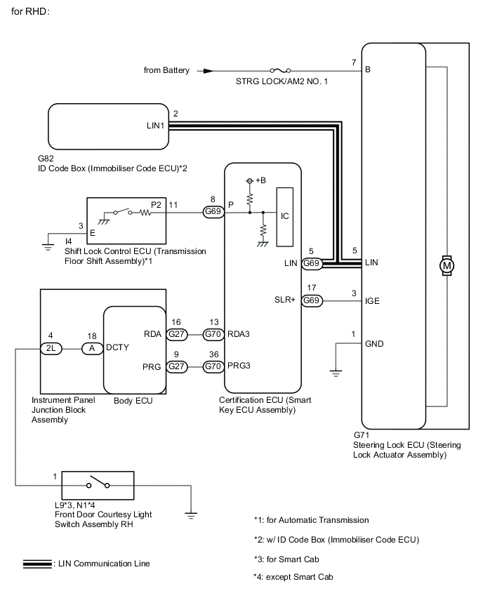
WIRING DIAGRAM
CAUTION / NOTICE / HINT
Note
-
When using the GTS with the vehicle engine switch off, connect the GTS to the vehicle and turn a courtesy light switch on and off at intervals of 1.5 seconds or less until communication between the GTS and the vehicle begins. Then select the Model Code "KEY REGIST" under manual mode and enter the following menus: Body Electrical / Entry & Start(CAN). While using the GTS, periodically turn a courtesy light switch on and off at intervals of 1.5 seconds or less to maintain communication between the GTS and the vehicle.
-
Perform either of the following operations to lock/unlock the steering:
-
To unlock the steering, carry the key and turn the engine switch on (ACC) or on (IG) with the shift lever in P*.
-
To lock the steering, turn the engine switch off with the shift lever in P* and then open a door.
-
*: for Automatic Transmission
-
Make sure that no DTCs are output. If any DTCs are output, proceed to the Diagnostic Trouble Code Chart.
-
The steering lock system uses LIN communication. First perform the inspections in "How to Proceed with Troubleshooting" to confirm that there are no communication malfunctions before proceeding with troubleshooting.
-
When replacing the steering lock ECU (steering lock actuator assembly), ID code box (immobiliser code ECU)* or certification ECU (smart key ECU assembly), registration must be performed (refer to the Service Bulletin).
-
*: w/ ID Code Box (Immobiliser Code ECU)
-
If the body ECU has been replaced, it is necessary to initialize the body ECU.
-
After performing repairs, confirm that the problem does not recur.
-
When disconnecting the cable from the negative (-) battery terminal, some systems need to be initialized after the cable is reconnected.
-
Inspect the fuses for circuits related to this system before performing the following procedure.
PROCEDURE
-
READ VALUE USING GTS (LOCK REQUEST RECEIVE)
-
Read the Data List according to the display on the GTS.
Body Electrical > Entry&Start > Data ListTester Display Measurement Item Range Normal Condition Diagnostic Note Lock Request Receive Lock request signal received state
Tech Tips
-
The reception state is maintained for 10 seconds.
-
When 10 seconds or more have elapsed after receiving the signal, the item changes to "NG".
OK or NG
-
OK: Within 10 seconds of opening any door with engine switch off and shift lever in P
NG: Except above
for Automatic Transmission
-
OK: Within 10 seconds of opening any door with engine switch off
NG: Except above
for Manual Transmission
If OK is not displayed even though the steering lock conditions are met, the certification ECU (smart key ECU assembly) may be malfunctioning.
Body Electrical > Entry&Start > Data ListTester Display Lock Request Receive OK The certification ECU (smart key ECU assembly) receives a lock request signal within 10 seconds of turning the engine switch from on (IG) to off and opening a door with the shift lever in P (for Automatic Transmission), and OK is displayed on the GTS screen. Result Proceed to OK (w/ ID Code Box (Immobiliser Code ECU)) OK (w/o ID Code Box (Immobiliser Code ECU)) NG -
OK (w/o ID Code Box (Immobiliser Code ECU)) 
READ VALUE USING GTS (L CODE CHECK) Click here
NG
INSPECT FRONT DOOR COURTESY LIGHT SWITCH ASSEMBLY Click here
OK (w/ ID Code Box (Immobiliser Code ECU)) 
-
-
READ VALUE USING GTS (S CODE CHECK)
-
Use the Data List to check if S code certification is functioning properly.
Body Electrical > Entry&Start > Data ListTester Display Measurement Item Range Normal Condition Diagnostic Note S Code Check Verification result between certification ECU (smart key ECU assembly) and ID code box (immobiliser code ECU) OK or NG OK: Verification result normal
NG: Verification result abnormal
When a malfunction is present:
-
The ID code for the certification ECU (smart key ECU assembly) or ID code box (immobiliser code ECU) is not registered, or the certification ECU (smart key ECU assembly) or ID code box (immobiliser code ECU) is malfunctioning.
-
The steering cannot be locked.
-
The steering cannot be unlocked (the engine cannot be started).
Body Electrical > Entry&Start > Data ListTester Display S Code Check OK OK is displayed on the GTS. Tech Tips
Reasons for verification failure:
-
The certification ECU (smart key ECU assembly) or ID code box (immobiliser code ECU) is malfunctioning.
-
There is a problem with the communication between ECUs.
-
An ECU is replaced, but is not registered.
-
An ECU is replaced with an ECU which has a code already stored in it.
Result Proceed to OK NG -
NG
REPLACE CERTIFICATION ECU (SMART KEY ECU ASSEMBLY) Click here
OK
-
-
READ VALUE USING GTS (L CODE CHECK)
-
Use the Data List to check if L code certification is functioning properly.
Body Electrical > Entry&Start > Data ListTester Display Measurement Item Range Normal Condition Diagnostic Note L Code Check Verification result between ID code box (immobiliser code ECU) and steering lock ECU (steering lock actuator assembly) OK or NG OK: Verification result normal
NG: Verification result abnormal
When a malfunction is present:
-
The ID code for the ID code box (immobiliser code ECU) or steering lock ECU (steering lock actuator assembly) is not registered, or the ID code box (immobiliser code ECU) or steering lock ECU (steering lock actuator assembly) is malfunctioning.
-
The steering cannot be locked.
-
The steering cannot be unlocked (the engine cannot be started).
Body Electrical > Entry&Start > Data ListTester Display L Code Check OK OK is displayed on the GTS. Tech Tips
Reasons for verification failure:
-
The steering lock ECU (steering lock actuator assembly) or ID code box (immobiliser code ECU) is malfunctioning.
-
There is a problem with the communication between ECUs.
-
An ECU is replaced, but is not registered.
-
An ECU is replaced with an ECU which has a code already stored in it.
Result Proceed to OK NG -
NG
REPLACE STEERING LOCK ECU (STEERING LOCK ACTUATOR ASSEMBLY) Click here
OK
-
-
CHECK HARNESS AND CONNECTOR (POWER SOURCE TERMINAL)
-
Disconnect the G71 steering lock ECU (steering lock actuator assembly) connector.
-

*a Front view of wire harness connector
(to Steering Lock ECU (Steering Lock Actuator Assembly))
Measure the resistance and voltage according to the value(s) in the table below.
Standard Resistance Tester Connection Condition Specified Condition G71-1 (GND) - Body ground Always Below 1 Ω Note
If the result is not as specified, check for looseness in the ground cable connection.
Standard Voltage Tester Connection Condition Specified Condition G71-7 (B) - Body ground Always 11 to 14 V Result Proceed to OK NG
NG 
REPAIR OR REPLACE HARNESS OR CONNECTOR
OK
-
-
INSPECT STEERING LOCK ECU (MOTOR ACTIVATION COMMAND SIGNAL)
-
Reconnect the G71 steering lock ECU (steering lock actuator assembly) connector.
-
Turn the engine switch off, make sure that the steering is unlocked and move the shift lever to P*.
-
*: for Automatic Transmission
-
-
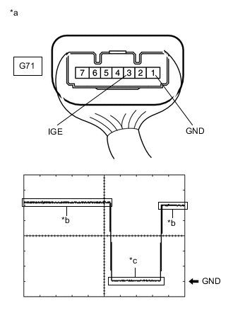
*a Component with harness connected
(Steering Lock ECU (Steering Lock Actuator Assembly))
*b Steering lock motor not operating *c Steering lock motor operating Check the signal waveform according to the condition(s) in the table below.
Standard Frequency Item Content Tester Connection G71-3 (IGE) - G71-1 (GND) Tool Setting 2 V/DIV., 200 ms./DIV. Vehicle Condition Steering lock motor not operating → Steering lock motor operating → Steering lock motor not operating Tech Tips
-
When taking measurements when the lock motor is stopped, it is not necessary to perform any operations.
-
In order to take measurements when the lock motor is operating, perform either of the following operations:
-
To unlock the steering, carry the key and turn the engine switch on (ACC) or on (IG) with the shift lever in P*.
-
To lock the steering, turn the engine switch off with the shift lever in P*, and then open a door.
-
*: for Automatic Transmission
Result Proceed to OK NG -
OK
REPLACE STEERING LOCK ECU (STEERING LOCK ACTUATOR ASSEMBLY) Click here
NG
CHECK HARNESS AND CONNECTOR (STEERING LOCK ECU (STEERING LOCK ACTUATOR ASSEMBLY) - CERTIFICATION ECU (SMART KEY ECU ASSEMBLY)) Click here
-
-
REPLACE CERTIFICATION ECU (SMART KEY ECU ASSEMBLY)
-
Replace the certification ECU (smart key ECU assembly) with a new one.
-
Perform registration.
Tech Tips
Refer to the Service Bulletin.
Result Proceed to NEXT
NEXT
-
-
READ VALUE USING GTS (S CODE CHECK)
-
Use the Data List to check if S code certification is functioning properly again.
Body Electrical > Entry&Start > Data ListTester Display Measurement Item Range Normal Condition Diagnostic Note S Code Check Verification result between certification ECU (smart key ECU assembly) and ID code box (immobiliser code ECU) OK or NG OK: Verification result normal
NG: Verification result abnormal
When a malfunction is present:
-
The ID code for the certification ECU (smart key ECU assembly) or ID code box (immobiliser code ECU) is not registered or the certification ECU (smart key ECU assembly) or ID code box (immobiliser code ECU) is malfunctioning.
-
The steering cannot be locked.
-
The steering cannot be unlocked (the engine cannot be started).
Body Electrical > Entry&Start > Data ListTester Display S Code Check OK OK is displayed on the GTS. Result Proceed to OK NG -
OK
END (CERTIFICATION ECU (SMART KEY ECU ASSEMBLY))
NG
REPLACE ID CODE BOX (IMMOBILISER CODE ECU)
-
-
REPLACE STEERING LOCK ECU (STEERING LOCK ACTUATOR ASSEMBLY)
-
Replace the steering lock ECU (steering lock actuator assembly) with a new one.
-
Perform registration.
Tech Tips
Refer to the Service Bulletin.
Result Proceed to NEXT
NEXT
-
-
READ VALUE USING GTS (L CODE CHECK)
-
Read the Data List according to the display on the GTS.
Body Electrical > Entry&Start > Data ListTester Display Measurement Item Range Normal Condition Diagnostic Note L Code Check Verification result between ID code box (immobiliser code ECU) and steering lock ECU (steering lock actuator assembly) OK or NG OK: Verification result normal
NG: Verification result abnormal
When a malfunction is present:
-
The ID code for the ID code box (immobiliser code ECU) or steering lock ECU (steering lock actuator assembly) is not registered or the certification ECU (smart key ECU assembly) or steering lock ECU (steering lock actuator assembly) is malfunctioning.
-
The steering cannot be locked.
-
The steering cannot be unlocked (the engine cannot be started).
Body Electrical > Entry&Start > Data ListTester Display L Code Check OK OK is displayed on the GTS. Result Proceed to OK NG -
OK
END (STEERING LOCK ECU (STEERING LOCK ACTUATOR ASSEMBLY))
NG
REPLACE ID CODE BOX (IMMOBILISER CODE ECU)
-
-
CHECK HARNESS AND CONNECTOR (STEERING LOCK ECU (STEERING LOCK ACTUATOR ASSEMBLY) - CERTIFICATION ECU (SMART KEY ECU ASSEMBLY))
-
Disconnect the G71 steering lock ECU (steering lock actuator assembly) connector.
-
Disconnect the G69 certification ECU (smart key ECU assembly) connector.
-
Check for deformation and corrosion of the connector case and terminals.
OK There is no deformation or corrosion of the connector case or terminals. -
Measure the resistance according to the value(s) in the table below.
Standard Resistance Tester Connection Condition Specified Condition G71-3 (IGE) - G69-17 (SLR+) Always Below 1 Ω G71-3 (IGE) - Body ground Always 10 kΩ or higher G69-17 (SLR+) - Body ground Always 10 kΩ or higher Result Proceed to OK NG
NG
REPAIR OR REPLACE HARNESS OR CONNECTOR
OK
-
-
INSPECT STEERING LOCK ECU (STEERING LOCK ACTUATOR ASSEMBLY)
-
Reconnect the G71 steering lock ECU (steering lock actuator assembly) connector.
-
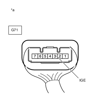
*a Component with harness connected
(Steering Lock ECU (Steering Lock Actuator Assembly))
Measure the voltage according to the value(s) in the table below.
Standard Voltage Tester Connection Condition Specified Condition G71-3 (IGE) - Body ground Always 11 to 14 V Result Proceed to OK NG
OK
REPLACE CERTIFICATION ECU (SMART KEY ECU ASSEMBLY)
NG
REPLACE STEERING LOCK ECU (STEERING LOCK ACTUATOR ASSEMBLY) Click here
-
-
READ VALUE USING GTS (L CODE CHECK)
-
Read the Data List according to the display on the GTS.
Body Electrical > Entry&Start > Data ListTester Display Measurement Item Range Normal Condition Diagnostic Note L Code Check Verification result between certification ECU (smart key ECU assembly) and steering lock ECU (steering lock actuator assembly) OK or NG OK: Verification result normal
NG: Verification result abnormal
When a malfunction is present:
-
The ID code for the certification ECU (smart key ECU assembly) or steering lock ECU (steering lock actuator assembly) is not registered or the certification ECU (smart key ECU assembly) or steering lock ECU (steering lock actuator) is malfunctioning.
-
The steering cannot be locked.
-
The steering cannot be unlocked (the engine cannot be started).
Body Electrical > Entry&Start > Data ListTester Display L Code Check OK OK is displayed on the GTS. Tech Tips
Reasons for verification failure:
-
The steering lock ECU (steering lock actuator assembly) or certification ECU (smart key ECU assembly) is malfunctioning.
-
There is a problem with the communication between ECUs.
-
An ECU is replaced, but is not registered.
-
An ECU is replaced with an ECU which has a code already stored in it.
Result Proceed to OK NG -
NG
REPLACE STEERING LOCK ECU (STEERING LOCK ACTUATOR ASSEMBLY) Click here
OK
-
-
CHECK HARNESS AND CONNECTOR (POWER SOURCE TERMINAL)
-
Disconnect the G71 steering lock ECU (steering lock actuator assembly) connector.
-
*a Front view of wire harness connector
(to Steering Lock ECU (Steering Lock Actuator Assembly))
Measure the resistance and voltage according to the value(s) in the table below.
Standard Resistance Tester Connection Condition Specified Condition G71-1 (GND) - Body ground Always Below 1 Ω Note
If the result is not as specified, check for looseness in the ground cable connection.
Standard Voltage Tester Connection Condition Specified Condition G71-7 (B) - Body ground Always 11 to 14 V Result Proceed to OK NG
NG
REPAIR OR REPLACE HARNESS OR CONNECTOR
OK
-
-
INSPECT STEERING LOCK ECU (MOTOR ACTIVATION COMMAND SIGNAL)
-
Reconnect the G71 steering lock ECU (steering lock actuator assembly) connector.
-
Turn the engine switch off, make sure that the steering is unlocked and move the shift lever to P*.
-
*: for Automatic Transmission
-
-
*a Component with harness connected
(Steering Lock ECU (Steering Lock Actuator Assembly))
*b Steering lock motor not operating *c Steering lock motor operating Check the signal waveform according to the condition(s) in the table below.
Standard Frequency Item Content Tester Connection G71-3 (IGE) - G71-1 (GND) Tool Setting 2 V/DIV., 200 ms./DIV. Vehicle Condition Steering lock motor not operating → Steering lock motor operating → Steering lock motor not operating Tech Tips
-
When taking measurements when the lock motor is stopped, it is not necessary to perform any operations.
-
In order to take measurements when the lock motor is operating, perform either of the following operations:
-
To unlock the steering, carry the key and turn the engine switch on (ACC) or on (IG) with the shift lever in P*.
-
To lock the steering, turn the engine switch off with the shift lever in P*, and then open a door.
-
*: for Automatic Transmission
Result Proceed to OK NG -
OK
REPLACE STEERING LOCK ECU (STEERING LOCK ACTUATOR ASSEMBLY) Click here
NG
CHECK HARNESS AND CONNECTOR (STEERING LOCK ECU (STEERING LOCK ACTUATOR ASSEMBLY) - CERTIFICATION ECU (SMART KEY ECU ASSEMBLY)) Click here
-
-
REPLACE STEERING LOCK ECU (STEERING LOCK ACTUATOR ASSEMBLY)
-
Replace the steering lock ECU (steering lock actuator assembly) with a new one.
-
Perform registration.
Tech Tips
Refer to the Service Bulletin.
Result Proceed to NEXT
NEXT
-
-
READ VALUE USING GTS (L CODE CHECK)
-
Read the Data List according to the display on the GTS.
Body Electrical > Entry&Start > Data ListTester Display Measurement Item Range Normal Condition Diagnostic Note L Code Check Verification result between certification ECU (smart key ECU assembly) and steering lock ECU (steering lock actuator assembly) OK or NG OK: Verification result normal
NG: Verification result abnormal
When a malfunction is present:
-
The ID code for the certification ECU (smart key ECU assembly) or steering lock ECU (steering lock actuator assembly) is not registered or the certification ECU (smart key ECU assembly) or steering lock ECU (steering lock actuator) is malfunctioning.
-
The steering cannot be locked.
-
The steering cannot be unlocked (the engine cannot be started).
Body Electrical > Entry&Start > Data ListTester Display L Code Check OK OK is displayed on the GTS. Result Proceed to OK NG -
OK
END (STEERING LOCK ECU (STEERING LOCK ACTUATOR ASSEMBLY) WAS DEFECTIVE)
NG
REPLACE CERTIFICATION ECU (SMART KEY ECU ASSEMBLY)
-
-
CHECK HARNESS AND CONNECTOR (STEERING LOCK ECU (STEERING LOCK ACTUATOR ASSEMBLY) - CERTIFICATION ECU (SMART KEY ECU ASSEMBLY))
-
Disconnect the G71 steering lock ECU (steering lock actuator assembly) connector.
-
Disconnect the G69 certification ECU (smart key ECU assembly) connector.
-
Check for deformation and corrosion of the connector case and terminals.
OK There is no deformation or corrosion of the connector case or terminals. -
Measure the resistance according to the value(s) in the table below.
Standard Resistance Tester Connection Condition Specified Condition G71-3 (IGE) - G69-17 (SLR+) Always Below 1 Ω G71-3 (IGE) - Body ground Always 10 kΩ or higher G69-17 (SLR+) - Body ground Always 10 kΩ or higher Result Proceed to OK NG
NG
REPAIR OR REPLACE HARNESS OR CONNECTOR
OK
-
-
INSPECT STEERING LOCK ECU (STEERING LOCK ACTUATOR ASSEMBLY)
-
Reconnect the G71 steering lock ECU (steering lock actuator assembly) connector.
-
*a Component with harness connected
(Steering Lock ECU (Steering Lock Actuator Assembly))
Measure the voltage according to the value(s) in the table below.
Standard Voltage Tester Connection Condition Specified Condition G71-3 (IGE) - Body ground Always 11 to 14 V Result Proceed to OK NG
OK
REPLACE CERTIFICATION ECU (SMART KEY ECU ASSEMBLY)
NG
REPLACE STEERING LOCK ECU (STEERING LOCK ACTUATOR ASSEMBLY) Click here
-
-
INSPECT FRONT DOOR COURTESY LIGHT SWITCH ASSEMBLY
-
Remove the front door courtesy light switch assembly.
for Double Cab: Click here
for Smart Cab: Click here
-
Inspect the front door courtesy light switch assembly.
for Double Cab: Click here
for Smart Cab: Click here
OK Front door courtesy light switch assembly is normal. Result Proceed to OK NG
NG
REPLACE FRONT DOOR COURTESY LIGHT SWITCH ASSEMBLY for Double Cab: Click here
REPLACE FRONT DOOR COURTESY LIGHT SWITCH ASSEMBLY for Smart Cab: Click hereOK
-
-
CHECK HARNESS AND CONNECTOR (FRONT DOOR COURTESY LIGHT SWITCH ASSEMBLY - INSTRUMENT PANEL JUNCTION BLOCK ASSEMBLY)
-
for LHD:
Disconnect the N2 front door courtesy light switch assembly LH connector.
-
for RHD (for Smart Cab):
Disconnect the L9 front door courtesy light switch assembly RH connector.
-
for RHD (except Smart Cab):
Disconnect the N1 front door courtesy light switch assembly RH connector.
-
Disconnect the 2L instrument panel junction block assembly connector.
-
Measure the resistance according to the value(s) in the table below.
Standard Resistance for LHD: Tester Connection Condition Specified Condition N2-1 - 2L-4 Always Below 1 Ω N2-1 - Body ground Always 10 kΩ or higher 2L-4 - Body ground Always 10 kΩ or higher for RHD (for Smart Cab): Tester Connection Condition Specified Condition L9-1 - 2L-4 Always Below 1 Ω L9-1 - Body ground Always 10 kΩ or higher 2L-4 - Body ground Always 10 kΩ or higher for RHD (except Smart Cab): Tester Connection Condition Specified Condition N1-1 - 2L-4 Always Below 1 Ω N1-1 - Body ground Always 10 kΩ or higher 2L-4 - Body ground Always 10 kΩ or higher Result Proceed to OK NG
NG
REPAIR OR REPLACE HARNESS OR CONNECTOR
OK
-
-
INSPECT INSTRUMENT PANEL JUNCTION BLOCK ASSEMBLY
-
Remove the instrument panel junction block assembly.
for LHD: Click here
for RHD: Click here
-
Remove the body ECU from the instrument panel junction block assembly.
for LHD: Click here
for RHD: Click here
-
Measure the resistance according to the value(s) in the table below.
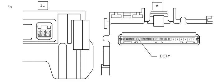
*a Component without harness connected
(Instrument Panel Junction Block Assembly)
- - Standard Resistance Tester Connection Condition Specified Condition 2L-4 - A-18 (DCTY) Always Below 1 Ω Result Proceed to OK NG
NG
REPLACE INSTRUMENT PANEL JUNCTION BLOCK ASSEMBLY for LHD: Click here
REPLACE INSTRUMENT PANEL JUNCTION BLOCK ASSEMBLY for RHD: Click hereOK
-
-
CHECK HARNESS AND CONNECTOR (CERTIFICATION ECU (SMART KEY ECU ASSEMBLY) - BODY ECU)
-
Disconnect the G70 certification ECU (smart key ECU assembly) connector.
-
Disconnect the G27 body ECU connector.
-
Measure the resistance according to the value(s) in the table below.
Standard Resistance Tester Connection Condition Specified Condition G70-13 (RDA3) - G27-16 (RDA) Always Below 1 Ω G70-13 (RDA3) - Body ground Always 10 kΩ or higher G27-16 (RDA) - Body ground Always 10 kΩ or higher G70-36 (PRG3) - G27-9 (PRG) Always Below 1 Ω G70-36 (PRG3) - Body ground Always 10 kΩ or higher G27-9 (PRG) - Body ground Always 10 kΩ or higher Result Proceed to OK NG
NG
REPAIR OR REPLACE HARNESS OR CONNECTOR
OK
-
-
REPLACE BODY ECU
-
Replace the body ECU with a new one.
for LHD: Click here
for RHD: Click here
Result Proceed to NEXT
NEXT
-
-
CHECK STEERING LOCK CONDITION
-
The engine switch is off.
-
for Automatic Transmission
The shift lever is in P.
-
A door is opened or a door lock operation (door lock, wireless door lock or key-linked lock operation*) is performed.
Tech Tips
*: This is the lock/unlock operation with the mechanical key.
-
Turn the steering wheel and check the steering condition.
OK Steering is locked. Result Proceed to OK NG (for Automatic Transmission) NG (for Manual Transmission)
OK
END (BODY ECU WAS DEFECTIVE)
NG (for Manual Transmission)
GO TO STEP 27 Click here
NG (for Automatic Transmission)
-
-
READ VALUE USING GTS (SHIFT P SIGNAL)
-
Move the shift lever to P.
-
Read the Data List according to the display on the GTS.
Body Electrical > Power Source Control > Data ListTester Display Measurement Item Range Normal Condition Diagnostic Note Shift P Signal Shift position (P) signal OK or NG ON: Shift lever in P
OFF: Shift lever not in P
-
Use this item to determine if the shift position switch is malfunctioning.
-
The engine cannot be started when this item is "OFF".
OK ON (shift lever in P) or OFF (shift lever not in P) appears on the screen according to the shift lever position. Result Proceed to OK NG -
NG
INSPECT SHIFT LOCK CONTROL ECU (TRANSMISSION FLOOR SHIFT ASSEMBLY) Click here
OK
-
-
CHECK STEERING LOCK CONDITION
-
The engine switch is off.
-
The shift lever is in P.
-
A door is opened or a door lock operation (door lock, wireless door lock or key-linked lock operation*) is performed.
Tech Tips
*: This is the lock/unlock operation with the mechanical key.
-
Turn the steering wheel and check the steering condition.
OK Steering is locked. Result Proceed to OK NG
OK
END (CONNECT CONNECTORS PROPERLY)
NG
-
-
READ VALUE USING GTS (STEERING LOCK, STEERING UNLOCK)
-
The steering is unlocked.
-
Read the Data List according to the display on the GTS.
Body Electrical > Entry&Start > Data ListTester Display Measurement Item Range Normal Condition Diagnostic Note Steering Lock Steering lock ECU (steering lock actuator assembly) lock confirmation status Set or Unset Set: Lock confirmed
Unset: Lock not confirmed
When Unset is displayed, the steering wheel is not locked. Steering Unlock Steering lock ECU (steering lock actuator assembly) unlock confirmation status Set or Unset Set: Unlock confirmed
Unset: Unlock not confirmed
When Unset is displayed, the steering wheel is not unlocked (the engine cannot be started). OK "Steering Lock" is "Unset" and "Steering Unlock" is "Set" Result Proceed to OK NG
NG
REPLACE STEERING LOCK ECU (STEERING LOCK ACTUATOR ASSEMBLY) Click here
OK
-
-
REPLACE CERTIFICATION ECU (SMART KEY ECU ASSEMBLY)
-
Replace the certification ECU (smart key ECU assembly) with a new one.
Tech Tips
Refer to the Service Bulletin.
-
Perform registration.
Tech Tips
Refer to the Service Bulletin.
Result Proceed to NEXT
NEXT
-
-
READ VALUE USING GTS (LOCK REQUEST RECEIVE)
-
Read the Data List according to the display on the GTS.
Body Electrical > Entry&Start > Data ListTester Display Measurement Item Range Normal Condition Diagnostic Note Lock Request Receive Lock request signal received state
Tech Tips
-
The reception state is maintained for 10 seconds.
-
When 10 seconds or more have elapsed after receiving the signal, the item changes to "NG".
OK or NG OK: Within 10 seconds of opening any door with engine switch off and shift lever in P*
NG: Except above
If OK is not displayed even though the steering lock conditions are met, the certification ECU (smart key ECU assembly) may be malfunctioning.
-
*: for Automatic Transmission
Body Electrical > Entry&Start > Data ListTester Display Lock Request Receive OK The certification ECU (smart key ECU assembly) receives a lock request signal within 10 seconds of turning the engine switch from on (IG) to off and opening a door with the shift lever in P (for Automatic Transmission), and OK is displayed on the GTS screen. Result Proceed to OK NG (w/ ID Code Box (Immobiliser Code ECU)) NG (w/o ID Code Box (Immobiliser Code ECU)) -
OK
END (CERTIFICATION ECU (SMART KEY ECU ASSEMBLY) WAS DEFECTIVE)
NG (w/ ID Code Box (Immobiliser Code ECU))
REPLACE ID CODE BOX (IMMOBILISER CODE ECU)
NG (w/o ID Code Box (Immobiliser Code ECU))
REPLACE STEERING LOCK ECU (STEERING LOCK ACTUATOR ASSEMBLY) Click here
-
-
INSPECT SHIFT LOCK CONTROL ECU (TRANSMISSION FLOOR SHIFT ASSEMBLY)
-
Disconnect the I4 shift lock control ECU (transmission floor shift assembly) connector.
-
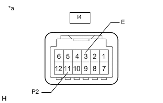
*a Component without harness connected
(Shift Lock Control ECU (Transmission Floor Shift Assembly))
Measure the resistance according to the value(s) in the table below.
Standard Resistance Tester Connection Condition Specified Condition Positive (+) tester probe → I4-11 (P2) Negative (-) tester probe → I4-3 (E) Shift lever in P 30 kΩ or higher Shift lever not in P Below 200 Ω Result Proceed to OK NG
NG
REPLACE SHIFT LOCK CONTROL ECU (TRANSMISSION FLOOR SHIFT ASSEMBLY)
OK
-
-
CHECK HARNESS AND CONNECTOR (SHIFT LOCK CONTROL ECU (TRANSMISSION FLOOR SHIFT ASSEMBLY) - CERTIFICATION ECU (SMART KEY ECU ASSEMBLY) AND BODY GROUND)
-
Disconnect the I4 shift lock control ECU (transmission floor shift assembly) connector.
-
Disconnect the G69 certification ECU (smart key ECU assembly) connector.
-
Measure the resistance according to the value(s) in the table below.
Standard Resistance Tester Connection Condition Specified Condition I4-11 (P2) - G69-8 (P) Always Below 1 Ω I4-3 (E) - Body ground Always Below 1 Ω I4-11 (P2) - Body ground Always 10 kΩ or higher G69-8 (P) - Body ground Always 10 kΩ or higher Result Proceed to OK NG
OK
END (CERTIFICATION ECU (SMART KEY ECU ASSEMBLY))
NG
REPAIR OR REPLACE HARNESS OR CONNECTOR
-