REAR BRAKE(for TMT Made 2WD) REASSEMBLY

CAUTION / NOTICE / HINT
Tech Tips
-
Use the same procedure for the RH and LH sides.
-
The procedure listed below is for the LH side.
PROCEDURE
-
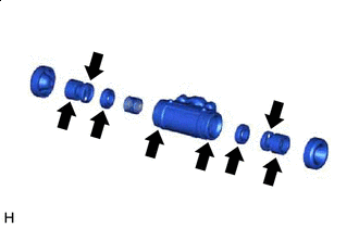
INSTALL REAR WHEEL CYLINDER CUP KIT

Lithium soap base glycol grease
-
Apply a light coat of lithium soap base glycol grease to 2 new rear wheel cylinder cups and 2 rear wheel cylinder pistons.
-
Install the 2 rear wheel cylinder cups to the 2 rear wheel cylinder pistons.
-
Install the rear brake wheel cylinder compression spring and 2 rear wheel cylinder pistons to the rear brake wheel cylinder.
-
Install 2 new rear wheel cylinder boots to the rear brake wheel cylinder.
-
-
TEMPORARILY INSTALL REAR BRAKE DRUM BLEEDER PLUG
-
Temporarily install the rear brake drum bleeder plug to the rear brake wheel cylinder assembly LH.
Tech Tips
The rear brake drum bleeder plug will be tightened to the torque specification in the "Bleed Brake Line" procedures.
-
-
INSTALL REAR BRAKE DRUM BLEEDER PLUG CAP
-
INSTALL REAR BRAKE WHEEL CYLINDER ASSEMBLY LH
-
Install the rear brake wheel cylinder assembly LH to the backing plate with the 2 bolts.
- Torque:
- 9.5 N*m { 97 kgf*cm, 84 in.*lbf }
-
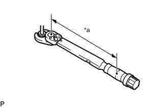
*a Torque Wrench Fulcrum Length Using a union nut wrench, connect the brake line to the rear brake wheel cylinder assembly LH.
- Torque:
- Specified tightening torque
- 15.2 N*m { 155 kgf*cm, 11 ft.*lbf }
Tech Tips
-
Calculate the torque wrench reading when changing the fulcrum length of the torque wrench.
-
When using a union nut wrench (fulcrum length of 22 mm (0.8661 in.)) + torque wrench (fulcrum length of 162 mm (6.3779 in.)): 13.4 N*m (137 kgf*cm, 10 ft.*lbf)
-
-
APPLY HIGH-TEMPERATURE GREASE
-
High-temperature grease Apply high-temperature grease to the surface of the backing plate which contacts the shoe.
-
-
INSTALL REAR BRAKE PARKING BRAKE SHOE LEVER SUB-ASSEMBLY
-
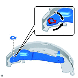

Install in this Direction Install the rear brake parking brake shoe lever sub-assembly with a new C-washer.
-
-
INSTALL REAR BRAKE AUTOMATIC ADJUST LEVER LH
-
Install the rear brake automatic adjust lever LH and rear brake automatic adjust lever tension spring to the front brake shoe.
-
-
INSTALL REAR BRAKE SHOE
-
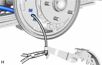
Using needle-nose pliers, connect the No. 3 parking brake cable assembly to the rear brake parking brake shoe lever sub-assembly.
-
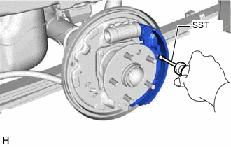
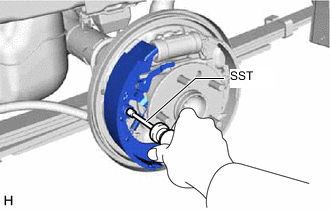
Using SST, install the shoe, pin, shoe hold down spring and shoe hold down spring cup.
- SST
- 09718-00011
-
-
INSTALL PARKING BRAKE SHOE STRUT SET LH
-
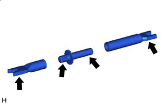
High-temperature grease Disassemble the parking brake shoe strut set LH. Apply high-temperature grease to the areas indicated by the arrows in the illustration. Then reassemble the parking brake shoe strut set LH.
-
Install the rear brake shoe return spring to the parking brake shoe strut set LH.
-
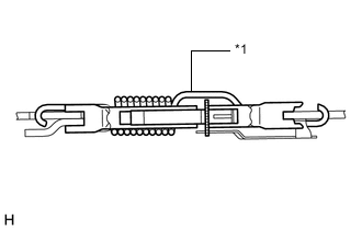
*1 Rear Brake Shoe Return Spring Install the parking brake shoe strut set LH as shown in the illustration.
-
-
INSTALL FRONT BRAKE SHOE
-
Connect the shoe tension spring to the front brake shoe and rear brake shoe.
-
Using SST, install the shoe, pin, shoe hold down spring and shoe hold down spring cup.
- SST
- 09718-00011
-
-
CONNECT REAR BRAKE SHOE RETURN SPRING
-
Connect the rear brake shoe return spring to the front brake shoe and rear brake shoe.
Note
Be careful not to damage the rear wheel cylinder boot.
-
-
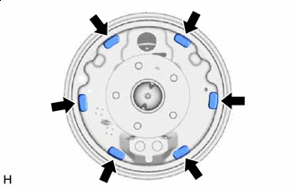
CHECK REAR BRAKE DRUM INSTALLATION
-
Check that each part is installed properly as shown in the illustration.
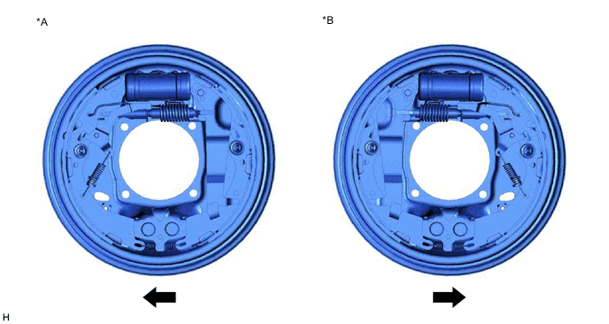
*A LH Side *B RH Side Front - - Note
There should be no oil or grease on the contact surfaces of the shoe lining and rear brake drum.
-