BRAKE PEDAL INSTALLATION
CAUTION / NOTICE / HINT
Tech Tips
-
Use the same procedure for RHD and LHD vehicles.
-
The procedure listed below is for LHD vehicles.
PROCEDURE
-
INSTALL STOP LIGHT SWITCH ASSEMBLY
-
INSTALL BRAKE PEDAL SUPPORT SUB-ASSEMBLY
-
Install the nut to the brake pedal support sub-assembly.
-
Install the brake pedal support sub-assembly with the 4 nuts.
- Torque:
- 18.4 N*m { 188 kgf*cm, 14 ft.*lbf }
-
Install the brake pedal support reinforcement set bolt.
- Torque:
- 18 N*m { 184 kgf*cm, 13 ft.*lbf }
-
Attach the 2 clamps to the brake pedal support sub-assembly.
-
Connect the connector to the stop light switch assembly.
-
-
INSTALL PUSH ROD PIN
-
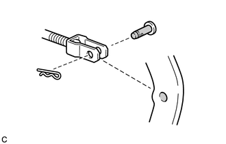

Lithium soap base glycol grease Apply a light coat of lithium soap base glycol grease to the push rod pin and installation hole of the brake pedal support sub-assembly.
-
Set the push rod clevis in place, insert the push rod pin from inside the vehicle, and then attach a new clip.
Note
After installation, check that the pedal operates smoothly.
-
-
INSTALL BRAKE PEDAL RETURN SPRING
-
Install the brake pedal return spring to the brake pedal support sub-assembly and push rod pin.
-
-
CHECK AND ADJUST BRAKE PEDAL HEIGHT
-
INSTALL UPPER INSTRUMENT PANEL SUB-ASSEMBLY
-
CONNECT CABLE TO NEGATIVE BATTERY TERMINAL
Note
When disconnecting the cable, some systems need to be initialized after the cable is reconnected.