| DTC Code | DTC Name |
|---|---|
| B1324 | Lost Communication with Meter |
DESCRIPTION
This DTC is stored when a communication error occurs between the navigation receiver assembly and combination meter assembly.
| DTC No. | Detection Item | DTC Detection Condition | Trouble Area |
|---|---|---|---|
| B1324 | Lost Communication with Meter | After the navigation receiver assembly receives a registration information signal, which is sent by the combination meter assembly when the ignition switch is ACC, 1 or more times, the navigation receiver assembly cannot receive the signal for 30 seconds or more. |
|
CAUTION / NOTICE / HINT
-
Check that the wire harness is properly installed and does not have any sharp bends, pinching or loose connections.
-
When replacing the combination meter assembly, make sure to replace it with a new one.
PROCEDURE
- Click here
CHECK HARNESS AND CONNECTOR (NAVIGATION RECEIVER ASSEMBLY - COMBINATION METER ASSEMBLY)
-
Disconnect the G114 navigation receiver assembly connector.
-
Disconnect the G9 combination meter assembly connector.
-
Measure the resistance according to the value(s) in the table below.
Standard Resistance Tester Connection Condition Specified Condition G114-3 (CNH1) - G9-38 (LCL+) Always Below 1 Ω G114-4 (CNL1) - G9-37 (LCL-) Always Below 1 Ω G114-3 (CNH1) - Body ground Always 10 kΩ or higher G114-4 (CNL1) - Body ground Always 10 kΩ or higher G114-3 (CNH1) - G114-4 (CNL1) Always 10 kΩ or higher -
Measure the voltage according to the value(s) in the table below.
Standard Voltage Tester Connection Condition Specified Condition G114-3 (CNH1) - Body ground Always Below 1 V G114-4 (CNL1) - Body ground Always Below 1 V Result Proceed to OK NG
- OKClick here
- NG
REPAIR OR REPLACE HARNESS OR CONNECTOR
-
- Click here
INSPECT COMBINATION METER ASSEMBLY
-
Remove the combination meter assembly.
-
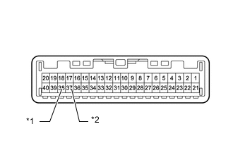
Table 1. *1 LCL+ *2 LCL- Measure the resistance according to the value(s) in the table below.
Standard Resistance Tester Connection Condition Specified Condition 38 (LCL+) - 37 (LCL-) Always 108 to 132 Ω Result Proceed to OK NG
- OKClick here
- NG
REPLACE COMBINATION METER ASSEMBLYClick here
-
- Click here
INSPECT NAVIGATION RECEIVER ASSEMBLY
-
Remove the navigation receiver assembly.
-
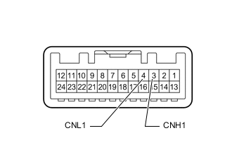
Measure the resistance according to the value(s) in the table below.
Standard Resistance Tester Connection Condition Specified Condition 3 (CNH1) - 4 (CNL1) Always 108 to 132 Ω Result Proceed to OK NG
- OKClick here
- NG
REPLACE NAVIGATION RECEIVER ASSEMBLYClick here
-
- Click here
CHECK COMBINATION METER ASSEMBLY
-
Replace the combination meter assembly.
-
Clear the DTCs.
- Body Electrical > Navigation System > Clear DTCs
-
-
-
Check for DTCs.
- Body Electrical > Navigation System > Trouble Codes
-
-
OK No DTCs are output. Result Proceed to OK NG
- OKClick here
- NG
REPLACE NAVIGATION RECEIVER ASSEMBLYClick here
-
- Click here
CHECK METER / GAUGE SYSTEM
-
Turn the ignition switch to ON and wait 30 seconds.
-
Operate the steering pad switch assembly and check that the audio tab is displayed on the multi-information display in the combination meter assembly and the audio system can be operated normally.
OK Audio system returns to normal. Result Proceed to OK NG
- OK
END (COMBINATION METER ASSEMBLY IS DEFECTIVE)
- NG
REPLACE NAVIGATION RECEIVER ASSEMBLYClick here
-