PROCEDURE
- Click here
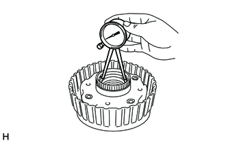
INSPECT DIRECT CLUTCH DRUM SUB-ASSEMBLY
-
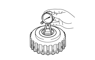
Using a caliper gauge, measure the inside diameter of the direct clutch drum sub-assembly bushing.
Standard inside diameter 59.515 to 59.540 mm (2.3432 to 2.3440 in.) If the inside diameter is not as specified, replace the direct clutch drum sub-assembly.
-
- Click here
INSPECT INPUT SHAFT SUB-ASSEMBLY
-
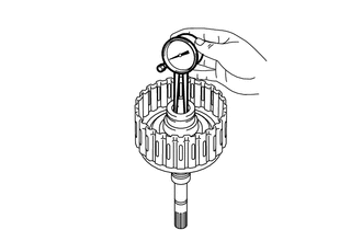
Using a caliper gauge, measure the inside diameter of the input shaft sub-assembly bushing.
Standard inside diameter 20.000 to 20.025 mm (0.7874 to 0.7883 in.) If the inside diameter is not as specified, replace the input shaft sub-assembly.
-
- Click here
INSPECT FORWARD CLUTCH HUB SUB-ASSEMBLY
-
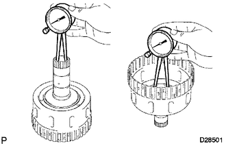
Using a caliper gauge, measure the inside diameter of the forward clutch hub sub-assembly bushing.
Standard inside diameter 26.037 to 26.062 mm (1.0251 to 1.0260 in.) If the inside diameter is not as specified, replace the forward clutch hub sub-assembly.
-
- Click here
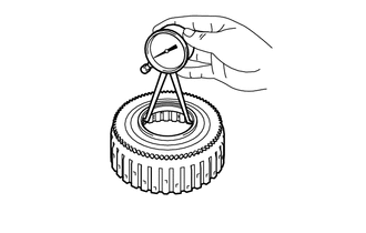
INSPECT SUN GEAR INPUT DRUM SUB-ASSEMBLY
-
Using a caliper gauge, measure the inside diameter of the sun gear input drum sub-assembly bushing.
Standard inside diameter 35.811 to 35.835 mm (1.4099 to 1.4108 in.) If the inside diameter is not as specified, replace the sun gear input drum sub-assembly.
-
- Click here
INSPECT FRONT PLANETARY GEAR ASSEMBLY
-
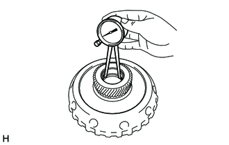
Using a caliper gauge, measure the inside diameter of the front planetary gear assembly bushing.
Standard inside diameter 35.811 to 35.835 mm (1.4099 to 1.4108 in.) If the inside diameter is not as specified, replace the front planetary gear assembly.
-
- Click here
INSPECT FRONT PLANETARY RING GEAR FLANGE SUB-ASSEMBLY
-
Using a caliper gauge, measure the inside diameter of the front planetary ring gear flange sub-assembly bushing.
Standard inside diameter 54.038 to 54.063 mm (2.1275 to 2.1284 in.) If the inside diameter is not as specified, replace the front planetary ring gear flange sub-assembly.
-
- Click here
INSPECT REAR PLANETARY RING GEAR FLANGE SUB-ASSEMBLY
-
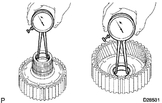
Using a caliper gauge, measure the inside diameter of the rear planetary ring gear flange sub-assembly bushing.
Standard inside diameter 32.176 to 32.201 mm (1.2668 to 1.2677 in.) If the inside diameter is not as specified, replace the rear planetary ring gear flange sub-assembly.
-
- Click here
INSPECT CENTER PLANETARY GEAR ASSEMBLY
-
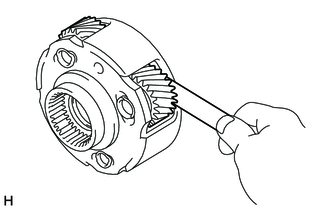
Using a feeler gauge, measure the center planetary gear pinion thrust clearance.
Standard clearance 0.12 to 0.68 mm (0.00473 to 0.0267 in.) If the clearance is not as specified, replace the center planetary gear assembly.
-
- Click here
INSPECT REAR PLANETARY GEAR ASSEMBLY
-
Using a feeler gauge, measure the rear planetary gear pinion thrust clearance.
Standard clearance 0.2 to 0.6 mm (0.00788 to 0.0236 in.) If the clearance is not as specified, replace the rear planetary gear assembly.
-
Using a caliper gauge, measure the inside diameter of the rear planetary gear bushing.
Standard inside diameter 20.000 to 20.025 mm (0.7874 to 0.7883 in.) If the inside diameter is not as specified, replace the rear planetary gear assembly.
-
- Click here
INSPECT NO. 3 ONE-WAY CLUTCH ASSEMBLY
-

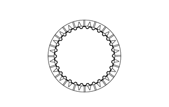
Lock 
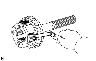
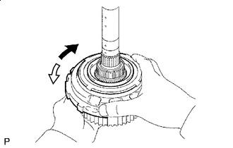
Free Hold the rear planetary ring gear and turn the No. 3 one-way clutch assembly.
-
Check that the No. 3 one-way clutch assembly turns freely when turned counterclockwise and locks when turned clockwise.
If there is a problem with the No. 3 one-way clutch assembly, replace it.
-
- Click here
INSPECT INTERMEDIATE SHAFT
-
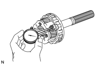
Using a dial indicator, check the intermediate shaft runout.
Standard runout 0.03 mm (0.00118 in.) If the runout is more than the standard, replace the intermediate shaft with a new one.
-
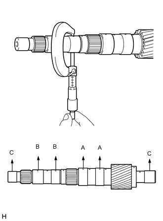
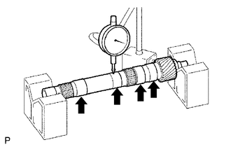
Using a micrometer, check the outer diameter of the intermediate shaft at each point shown in the illustration.
Standard diameter A 32.062 to 32.075 mm (1.2623 to 1.2627 in.) B 25.962 to 25.975 mm (1.0222 to 1.0226 in.) C 19.963 to 19.976 mm (0.7860 to 0.7864 in.) If the outer diameter is more than the standard, replace the intermediate shaft with a new one.
-
- Click here
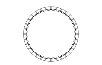
INSPECT FORWARD CLUTCH RETURN SPRING SUB-ASSEMBLY
-
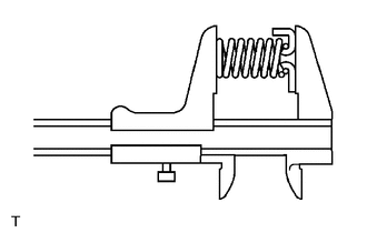
Using a vernier caliper, measure the free length of the forward clutch return spring sub-assembly including the spring seat.
Standard free length 26.74 mm (1.053 in.) If the free length is more than the standard free length, replace the forward clutch return spring sub-assembly.
-
- Click here
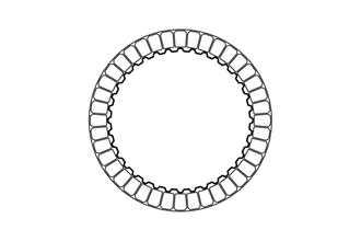
INSPECT DIRECT CLUTCH RETURN SPRING SUB-ASSEMBLY
-
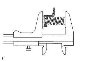
Using a vernier caliper, measure the free length of the direct clutch return spring sub-assembly including the spring seat.
Standard free length 22.14 mm (0.872 in.) If the free length is more than the standard free length, replace the direct clutch return spring sub-assembly.
-
- Click here
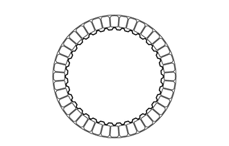
INSPECT NO. 1 BRAKE PISTON RETURN SPRING SUB-ASSEMBLY
-
Using a vernier caliper, measure the free length of the No. 1 brake piston return spring sub-assembly including the spring seat.
Standard free length 16.72 mm (0.658 in.) If the free length is more than the standard free length, replace the No. 1 brake piston return spring sub-assembly.
-
- Click here
INSPECT NO. 2 BRAKE PISTON RETURN SPRING SUB-ASSEMBLY
-
Using a vernier caliper, measure the free length of the No. 2 brake piston return spring sub-assembly including the spring seat.
Standard free length 16.68 mm (0.657 in.) If the free length is more than the standard free length, replace the No. 2 brake piston return spring sub-assembly.
-
- Click here
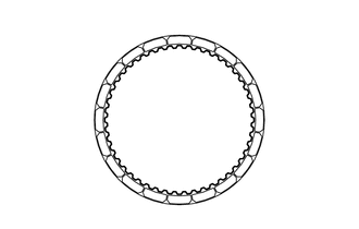
INSPECT 1ST AND REVERSE BRAKE RETURN SPRING SUB-ASSEMBLY
-
Using a vernier caliper, measure the free length of the 1st and reverse brake return spring sub-assembly including the spring seat.
Standard free length 23.74 mm (0.935 in.) If the free length is more than the standard free length, replace the 1st and reverse return spring sub-assembly.
-
- Click here
INSPECT NO. 1 CLUTCH DISC (FORWARD CLUTCH DISC)
-
Check if the contact surfaces of the No. 1 clutch discs, No. 1 clutch plates and No. 1 clutch flange are worn or burnt.
If necessary, replace them.
Note:
-
If the lining of any No. 1 clutch disc is peeled or discolored, or even if part of a groove is damaged, replace all the No. 1 clutch discs.
-
Before installing new No. 1 clutch discs, soak them in ATF for at least 15 minutes.
-
-
- Click here
INSPECT NO. 2 CLUTCH DISC (DIRECT CLUTCH DISC)
-
Check if the contact surfaces of the No. 2 clutch discs, No. 2 clutch plates and No. 2 clutch flange are worn or burnt.
If necessary, replace them.
Note:
-
If the lining of any No. 2 clutch disc is peeled or discolored, or even if part of a groove is damaged, replace all the No. 2 clutch discs.
-
Before installing new No. 2 clutch discs, soak them in ATF for at least 15 minutes.
-
-
- Click here
INSPECT NO. 1 BRAKE DISC
-
Check if the contact surfaces of the No. 1 brake discs, No. 1 brake plates and No. 1 brake flange are worn or burnt.
If necessary, replace them.
Note:
-
If the lining of any No. 1 brake disc is peeled or discolored, or even if part of a groove is damaged, replace all the No. 1 brake discs.
-
Before installing new No. 1 brake discs, soak them in ATF for at least 15 minutes.
-
-
- Click here
INSPECT NO. 2 BRAKE DISC
-
Check if the contact surfaces of the No. 2 brake discs, No. 2 brake plates and No. 2 brake flanges are worn or burnt.
If necessary, replace them.
Note:
-
If the lining of any No. 2 brake disc is peeled or discolored, or even if part of a groove is damaged, replace all the No. 2 brake discs.
-
Before installing new No. 2 brake discs, soak them in ATF for at least 15 minutes.
-
-
- Click here
INSPECT NO. 4 BRAKE DISC
-
Check if the contact surfaces of the No. 4 brake discs, No. 4 brake plates and No. 4 brake flanges are worn or burnt.
If necessary, replace them.
Note:
-
If the lining of any No. 4 brake disc is peeled or discolored, or even if part of a groove is damaged, replace all the No. 4 brake discs.
-
Before installing new No. 4 brake discs, soak them in ATF for at least 15 minutes.
-
-
- Click here
INSPECT CLEARANCE OF NO. 1 CLUTCH (FORWARD CLUTCH)
-
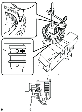
*1 Selected Forward Clutch Flange *a Oil Hole Using a dial indicator, measure the clearance of the No. 1 clutch at several points while applying compressed air (196 kPa, 2.0 kgf/cm2, 28 psi) to the oil hole as shown in the illustration, and calculate the average.
Standard clearance 0.75 to 1.05 mm (0.0296 to 0.0413 in.) If the clearance is not as specified, select and install an appropriate forward clutch flange that will bring the clearance within the specified range.
Tip:There are forward clutch flanges of different thicknesses.
Forward Clutch Flange Thickness Part No. Thickness (mm (in.)) 35635-71010 3.0 (0.118) 35635-71020 3.1 (0.122) 35635-71030 3.2 (0.126) 35635-71040 3.3 (0.130) 35635-71050 3.4 (0.134) 35635-71060 3.5 (0.138) 35635-71070 3.6 (0.142) 35635-71080 3.7 (0.146) 35635-71090 3.8 (0.150) 35635-71100 3.9 (0.154) 35635-71110 4.0 (0.157) 35635-71120 4.1 (0.161) 35635-71130 4.2 (0.165)
-
- Click here
INSPECT CLEARANCE OF NO. 2 CLUTCH (DIRECT CLUTCH)
-
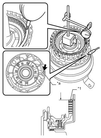
*1 Selected Direct Clutch Flange *a Oil Hole Using a dial indicator, measure the clearance of the No. 2 clutch at several points while applying compressed air (196 kPa, 2.0 kgf/cm2, 28 psi) to the oil hole as shown in the illustration, and calculate the average.
Standard clearance 0.5 to 0.8 mm (0.0197 to 0.0314 in.) If the clearance is not as specified, select and install an appropriate direct clutch flange that will bring the clearance within the specified range.
Tip:There are direct clutch flanges of different thicknesses.
Direct Clutch Flange Thickness Part No. Thickness (mm (in.)) 35675-71010 3.0 (0.118) 35675-71020 3.1 (0.122) 35675-71030 3.2 (0.126) 35675-71040 3.3 (0.130) 35675-71050 3.4 (0.134) 35675-71060 3.5 (0.138) 35675-71070 3.6 (0.142) 35675-71080 3.7 (0.146) 35675-71090 3.8 (0.150)
-
- Click here
INSPECT CLEARANCE OF NO. 1 BRAKE
-
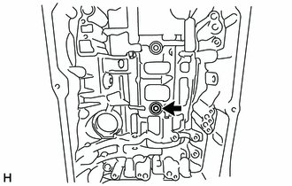
Make sure that the No. 1 brake piston moves smoothly when applying and releasing compressed air (392 kPa, 4.0 kgf/cm2, 57 psi).
-
*1 Selected No. 1 Brake Flange Using a feeler gauge, measure the No. 1 brake pack clearance between the No. 1 brake disc and No. 1 brake flange.
Standard clearance 0.4 to 0.7 mm (0.0158 to 0.0275 in.) If the clearance is not as specified, select and install an appropriate No. 1 brake flange that will bring the clearance within the specified range.
No. 1 Brake Flange Thickness Mark Thickness (mm (in.)) 0 4.9 (0.193) 1 5.0 (0.197) 2 5.1 (0.201) 3 5.2 (0.205) 4 5.3 (0.209) 5 5.4 (0.213) 6 5.5 (0.217) 7 5.6 (0.220) 8 5.7 (0.224) A 5.8 (0.228)
-
- Click here
INSPECT CLEARANCE OF NO. 2 BRAKE
-
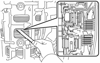
Make sure that the No. 2 brake piston moves smoothly when applying and releasing compressed air (392 kPa, 4.0 kgf/cm2, 57 psi).
-
*1 Selected No. 2 Brake Flange Using a feeler gauge, measure the No. 2 brake pack clearance between the No. 2 brake disc and No. 2 brake flange.
Standard clearance 0.5 to 0.8 mm (0.0197 to 0.0314 in.) If the clearance is not as specified, select and install an appropriate No. 2 brake flange that will bring the clearance within the specified range.
No. 2 Brake Flange Thickness Mark Thickness (mm (in.)) 0 2.0 (0.0787) 1 2.1 (0.0827) 2 2.2 (0.0866) 3 2.3 (0.0906) 4 2.4 (0.0945) 5 2.5 (0.0984) 6 2.6 (0.102) 7 2.7 (0.106) 8 2.8 (0.110)
-
- Click here
INSPECT CLEARANCE OF NO. 4 BRAKE
-
Make sure that the 1st and reverse brake piston moves smoothly when applying and releasing compressed air (392 kPa, 4.0 kgf/cm2, 57 psi).
-
*1 Selected No. 4 Brake Flange Using a feeler gauge, measure the No. 4 brake pack clearance between the No. 4 brake disc and No. 4 brake flange.
Standard clearance 0.7 to 1.0 mm (0.0276 to 0.0393 in.) If the clearance is not as specified, select and install an appropriate No. 4 brake flange that will bring the clearance within the specified range.
No. 4 Brake Flange Thickness Mark Thickness (mm (in.)) 0 1.80 (0.0709) 1 1.97 (0.0776) 3 2.11 (0.0831) 4 2.25 (0.0886) 5 2.39 (0.0941) 7 2.53 (0.0996) 8 2.67 (0.105) 10 2.81 (0.111) 11 2.95 (0.116) 12 3.09 (0.122) 14 3.23 (0.127)
-