CAUTION / NOTICE / HINT
The necessary procedures (adjustment, calibration, initialization, or registration) that must be performed after parts are removed, installed, or replaced during the automatic transmission assembly removal/installation are shown below.
| Replacement Part or Procedure | Necessary Procedures | Effects/Inoperative when not Performed | Link |
|---|---|---|---|
|
|
|
-
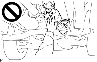
To prevent burns, do not touch the engine, exhaust pipe or other high temperature components while the engine is hot.
-
The automatic transmission assembly is very heavy. Be sure to follow the procedure described in the repair manual, or the transmission jack may suddenly drop or a part may fall.
PROCEDURE
- Click here
PRECAUTION
Note:After turning the ignition switch off, waiting time may be required before disconnecting the cable from the battery terminal. Therefore, make sure to read the disconnecting the cable from the battery terminal notice before proceeding with work.
- Click here
DISCONNECT CABLE FROM NEGATIVE BATTERY TERMINAL
Note:When disconnecting the cable, some systems need to be initialized after the cable is reconnected.
- Click here
DRAIN AUTOMATIC TRANSMISSION FLUID
- Click here
REMOVE PROPELLER WITH CENTER BEARING SHAFT ASSEMBLY
- Click here
REMOVE STARTER ASSEMBLY
- Click here
REMOVE EXHAUST MANIFOLD SUB-ASSEMBLY LH
- Click here
REMOVE EXHAUST MANIFOLD SUB-ASSEMBLY RH
- Click here
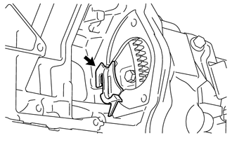
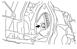
DISCONNECT TRANSMISSION CONTROL CABLE ASSEMBLY
-
Remove the clip, nut and disconnect the transmission control cable assembly from the transmission control shaft lever LH and transmission control cable bracket.
-
- Click here
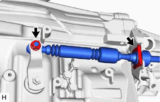
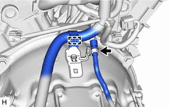
DISCONNECT OIL COOLER TUBE
-
Disconnect the 2 oil cooler tubes from the automatic transmission assembly.
Tip:Use a container to catch any ATF which flows out of the 2 oil cooler tubes and automatic transmission assembly.
-
Remove the 2 bolts and disconnect the 2 oil cooler tubes from the 2 oil cooler tube clamps.
-
Remove the 2 bolts and 2 oil cooler tube clamps from the automatic transmission assembly and engine assembly.
Tip:It is not necessary to remove the oil cooler tube clamps unless they are being replaced.
-
- Click here
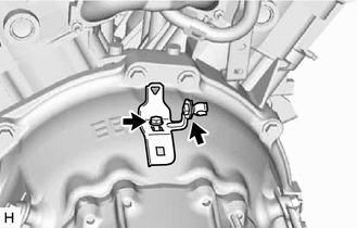
DISCONNECT GROUND WIRE
-
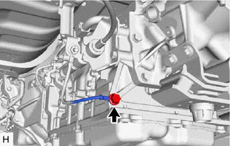
Remove the bolt and disconnect the ground wire from the automatic transmission assembly.
-
- Click here
REMOVE TRANSMISSION INSULATOR RH
- Click here
REMOVE FLYWHEEL HOUSING SIDE COVER
-
Remove the flywheel housing side cover from the engine assembly.
-
- Click here
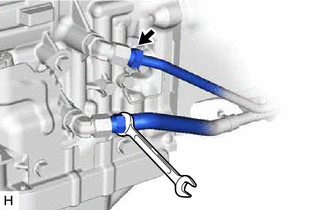
REMOVE DRIVE PLATE AND TORQUE CONVERTER ASSEMBLY SETTING BOLT
-
Turn the crankshaft to gain access to the locations of the 6 drive plate and torque converter assembly setting bolts and remove each bolt while holding the crankshaft pulley bolt with a wrench.
-
- Click here
REMOVE NO. 2 FRAME CROSSMEMBER SUB-ASSEMBLY
-
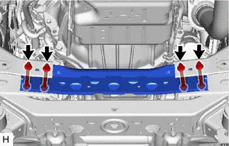
Remove the 4 bolts, 4 nuts and No. 2 frame crossmember sub-assembly from the vehicle body.
-
- Click here
SUPPORT AUTOMATIC TRANSMISSION ASSEMBLY
-
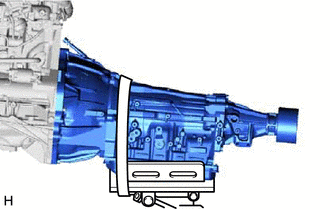
Support the automatic transmission assembly with a transmission jack.
Note:
-
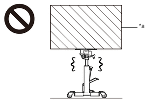
In order to protect the automatic transmission oil pan sub-assembly, place attachments on the transmission jack.
-
Make sure that the attachments and the automatic transmission oil pan sub-assembly are centered on the transmission jack.
-
To prevent the automatic transmission oil pan sub-assembly from deforming, do not place any attachments under the automatic transmission oil pan sub-assembly of the automatic transmission assembly.
-
Secure the automatic transmission assembly to the transmission jack using a belt, etc. to prevent it from falling.
-
-
- Click here
REMOVE NO. 3 FRAME CROSSMEMBER SUB-ASSEMBLY
-
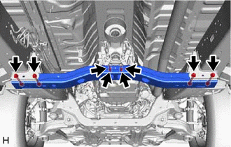
Remove the 4 bolts and disconnect the No. 3 frame crossmember sub-assembly from the rear engine mounting insulator.
-
Remove the 4 bolts, 4 nuts and No. 3 frame crossmember sub-assembly from the vehicle body.
-
- Click here
REMOVE REAR ENGINE MOUNTING INSULATOR
Tip:It is not necessary to remove the rear engine mounting insulator unless it is being replaced.
-
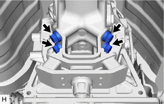
Remove the 4 bolts and rear engine mounting insulator from the automatic transmission assembly.
-
- Click here
REMOVE TRANSMISSION BREATHER BRACKET
-
Tilt down the automatic transmission assembly.
Note:Make sure that the cooling fan and fan shroud do not contact the engine assembly when tilting the automatic transmission assembly.
-
Disconnect the breather hose and detach the wire harness clamp from the transmission breather bracket.
-
Remove the bolt and transmission breather bracket from the automatic transmission assembly.
-
Remove the clamp from the transmission breather bracket.
Tip:It is not necessary to remove the transmission clamps they are being replaced.
-
- Click here
DISCONNECT WIRE HARNESS
-
Disconnect the breather hose from the wire harness.
-
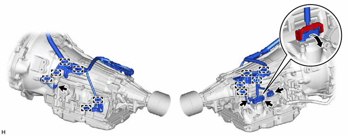
Disconnect the park/neutral position switch connector, transmission wire connector and 2 transmission revolution sensor connectors.
Tip:Detach the claw, press down the lever, and then disconnect the transmission wire connector.
-
Detach the heated oxygen sensor connector from the wire harness clamp bracket.
-
Detach the 11 wire harness clamps.
-
- Click here
REMOVE AUTOMATIC TRANSMISSION ASSEMBLY
-
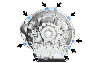
Remove the 9 bolts and automatic transmission assembly from the engine assembly.
Note:To prevent damage to the 2 knock pins, do not pry between the automatic transmission assembly and engine assembly.
-
- Click here
REMOVE WIRE HARNESS CLAMP BRACKET
Tip:It is not necessary to remove the wire harness clamp brackets unless they are being replaced.
-
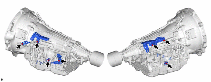
Remove the 7 bolts and 6 wire harness clamp brackets from the automatic transmission assembly.
-
- Click here
REMOVE TRANSMISSION CONTROL CABLE BRACKET
Tip:It is not necessary to remove the transmission control cable bracket unless it is being replaced.
-
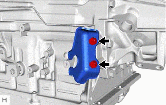
Remove the 2 bolts and transmission control cable bracket from the automatic transmission assembly.
-
- Click here
REMOVE TORQUE CONVERTER ASSEMBLY
-
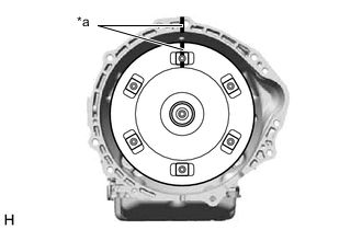
*a Matchmark Put matchmarks on the automatic transmission assembly and the torque converter assembly.
-
Remove the torque converter assembly from the automatic transmission assembly.
Note:Remove the torque converter assembly from the input shaft horizontally.
-
- Click here
INSPECT TORQUE CONVERTER ASSEMBLY
- Click here
INSPECT DRIVE PLATE