AUTOMATIC TRANSMISSION SYSTEM(for 2GD-FTV) Transmission Control Switch Circuit
DESCRIPTION
After moving the shift lever to S, it is possible to switch the shift range between "1" (S1 range) and "6" (S6 range) using the transmission control switch.
Moving the shift lever to "+" once raises the shift range by one, and moving the shift lever to "-" once lowers the shift range by one.
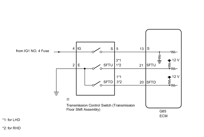
WIRING DIAGRAM
CAUTION / NOTICE / HINT
Note
Inspect the fuses for circuits related to this system before performing the following procedure.
PROCEDURE
-
READ VALUE USING GTS (SPORTS MODE SELECTION SW)
-
Connect the GTS to the DLC3.
-
Turn the ignition switch to ON.
-
Turn the GTS on.
-
Enter the following menus: Powertrain / Engine and ECT / Data List.
-
In accordance with the display on the GTS, read the Data List.
Powertrain > Engine > Data ListTester Display Measurement Item Range Normal Condition Diagnostic Note Sports Mode Selection SW Sport mode select switch status ON or OFF
-
ON: Shift lever in S, "+" or "-"
-
OFF: Shift lever not in S, "+" or "-"
-
Powertrain > Engine > Data ListTester Display Sports Mode Selection SW Result Result Proceed to Data display is within Normal Condition range A Data display is not within Normal Condition range B -
B 
INSPECT TRANSMISSION CONTROL SWITCH (TRANSMISSION FLOOR SHIFT ASSEMBLY) Click here
A 
-
-
READ VALUE USING GTS (SPORTS SHIFT UP SW AND SPORTS SHIFT DOWN SW)
-
Connect the GTS to the DLC3.
-
Turn the ignition switch to ON.
-
Turn the GTS on.
-
Enter the following menus: Powertrain / Engine and ECT / Data List.
-
In accordance with the display on the GTS, read the Data List.
Powertrain > Engine > Data ListTester Display Measurement Item Range Normal Condition Diagnostic Note Sports Shift Up SW Sport shift up switch status ON or OFF
-
ON: Shift lever held in "+" (up-shift)
-
OFF: Shift lever not held in "+" (up-shift)
- Sports Shift Down SW Sport shift down switch status ON or OFF
-
ON: Shift lever held in "-" (down-shift)
-
OFF: Shift lever not held in "-" (down-shift)
-
Powertrain > Engine > Data ListTester Display Sports Shift Up SW Sports Shift Down SW Result Result Proceed to Data display is within Normal Condition range A Data display is not within Normal Condition range B -
A 
PROCEED TO NEXT SUSPECTED AREA SHOWN IN PROBLEM SYMPTOMS TABLE Click here
B
-
-
INSPECT TRANSMISSION CONTROL SWITCH (TRANSMISSION FLOOR SHIFT ASSEMBLY)
-
Disconnect the transmission control switch connector.
-
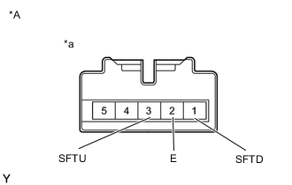
*A for LHD *a Component without harness connected
(Transmission Control Switch)
for LHD:
Measure the resistance according to the value(s) in the table below.
Standard Resistance Tester Connection Condition Specified Condition 3 (SFTU) - 2 (E) Shift lever held in "+" (Up-shift) Below 1 Ω 1 (SFTD) - 2 (E) Shift lever held in "-" (Down-shift) Below 1 Ω 3 (SFTU) - 2 (E) Shift lever not held in "+" (Up-shift) 10 kΩ or higher 1 (SFTD) - 2 (E) Shift lever not held in "-" (Down-shift) 10 kΩ or higher -
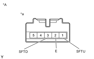
*A for RHD *a Component without harness connected
(Transmission Control Switch)
for RHD:
Measure the resistance according to the value(s) in the table below.
Standard Resistance Tester Connection Condition Specified Condition 1 (SFTU) - 2 (E) Shift lever held in "+" (Up-shift) Below 1 Ω 3 (SFTD) - 2 (E) Shift lever held in "-" (Down-shift) Below 1 Ω 1 (SFTU) - 2 (E) Shift lever not held in "+" (Up-shift) 10 kΩ or higher 3 (SFTD) - 2 (E) Shift lever not held in "-" (Down-shift) 10 kΩ or higher Result Proceed to OK NG
NG
REPLACE TRANSMISSION CONTROL SWITCH (TRANSMISSION FLOOR SHIFT ASSEMBLY) Click here
OK
-
-
CHECK HARNESS AND CONNECTOR (TRANSMISSION CONTROL SWITCH - BODY GROUND)
-
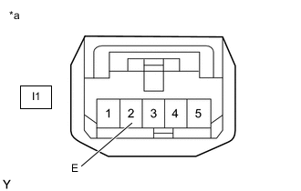
*a Front view of wire harness connector
(to Transmission Control Switch)
Disconnect the transmission control switch connector.
-
Measure the resistance according to the value(s) in the table below.
Standard Resistance Tester Connection Condition Specified Condition I1-2 (E) - Body ground Always Below 1 Ω Result Proceed to OK NG
NG
REPAIR OR REPLACE HARNESS OR CONNECTOR
OK
-
-
CHECK HARNESS AND CONNECTOR (TRANSMISSION CONTROL SWITCH - ECM)
-
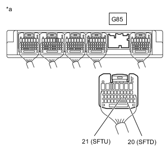
*a Rear view of wire harness connector
(to ECM)
Disconnect the ECM connector.
-
Measure the resistance according to the value(s) in the table below.
Standard Resistance Tester Connection Condition Specified Condition G85-21 (SFTU) - Body ground Shift lever held in "+" (Up-shift) Below 1 Ω G85-20 (SFTD) - Body ground Shift lever held in "-" (Down-shift) Below 1 Ω G85-21 (SFTU) - Body ground Shift lever not held in "+" 10 kΩ or higher G85-20 (SFTD) - Body ground Shift lever not held in "-" 10 kΩ or higher Result Proceed to OK NG
OK
PROCEED TO NEXT SUSPECTED AREA SHOWN IN PROBLEM SYMPTOMS TABLE Click here
NG
REPAIR OR REPLACE HARNESS OR CONNECTOR
-
-
INSPECT TRANSMISSION CONTROL SWITCH (TRANSMISSION FLOOR SHIFT ASSEMBLY)
-
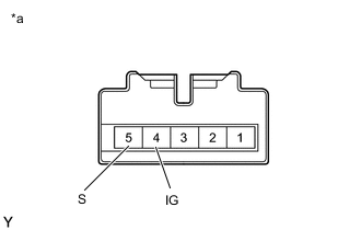
*a Component without harness connected
(Transmission Control Switch)
Disconnect the transmission control switch connector.
-
Measure the resistance according to the value(s) in the table below.
Standard Resistance Tester Connection Condition Specified Condition 4 (IG) - 5 (S) Shift lever in S, "+" or "-" Below 1 Ω 4 (IG) - 5 (S) Shift lever not in S, "+" or "-" 10 kΩ or higher Result Proceed to OK NG
NG
REPLACE TRANSMISSION CONTROL SWITCH (TRANSMISSION FLOOR SHIFT ASSEMBLY) Click here
OK
-
-
CHECK HARNESS AND CONNECTOR (BATTERY - TRANSMISSION CONTROL SWITCH)
-
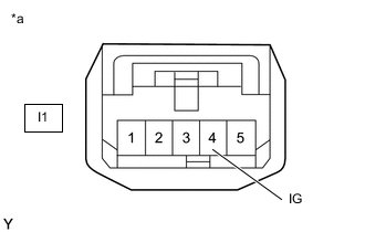
*a Front view of wire harness connector
(to Transmission Control Switch)
Disconnect the transmission control switch connector.
-
Measure the voltage according to the value(s) in the table below.
Standard Voltage Tester Connection Switch Condition Specified Condition I1-4 (IG) - Body ground Ignition switch ON 11 to 14 V I1-4 (IG) - Body ground Ignition switch off Below 1 V Result Proceed to OK NG
NG
REPAIR OR REPLACE HARNESS OR CONNECTOR
OK
-
-
CHECK HARNESS AND CONNECTOR (TRANSMISSION CONTROL SWITCH - ECM)
-
Disconnect the I1 transmission control switch connector.
-
Disconnect the G85 ECM connector.
-
Measure the resistance according to the value(s) in the table below.
Standard Resistance Tester Connection Condition Specified Condition I1-5 (S) - G85-13 (S) Always Below 1 Ω I1-5 (S) - Body ground Always 10 kΩ or higher G85-13 (S) - Body ground Always 10 kΩ or higher Result Proceed to OK NG
OK
PROCEED TO NEXT SUSPECTED AREA SHOWN IN PROBLEM SYMPTOMS TABLE Click here
NG
REPAIR OR REPLACE HARNESS OR CONNECTOR
-