AUTOMATIC TRANSMISSION UNIT REASSEMBLY

PROCEDURE
-
BEARING POSITION
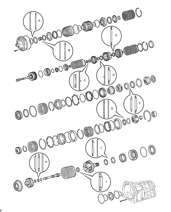
Bearing and Race Diameter Mark Front Race Diameter Inside/Outside Thrust Bearing Diameter Inside/Outside Rear Race Diameter Inside/Outside A 74.2 mm (2.92 in.) / 87.74 mm (3.45 in.) 71.9 mm (2.83 in.) / 85.6 mm (3.37 in.) - B 37.0 mm (1.46 in.) / 52.3 mm (2.06 in.) 34.6 mm (1.36 in.) / 52.0 mm (2.05 in.) - C - 21.3 mm (0.839 in.) / 41.1 mm (1.62 in.) 22.6 mm (0.890 in.) / 45.0 mm (1.77 in.) D 38.4 mm (1.51 in.) / 56.5 mm (2.22 in.) 33.3 mm (1.31 in.) / 51.5 mm (2.03 in.) - E - 42.5 mm (1.67 in.) / 61.2 mm (2.41 in.) - F 38.0 mm (1.50 in.) / 57.0 mm (2.24 in.) 43.4 mm (1.71 in.) / 58.3 mm (2.30 in.) - G - 55.7 mm (2.19 in.) / 76.4 mm (3.01 in.) 53.7 mm (2.11 in.) / 74.0 mm (2.91 in.) H 33.4 mm (1.31 in.) / 49.0 mm (1.93 in.) 32.1 mm (1.26 in.) / 49.35 mm (1.94 in.) 32.1 mm (1.26 in.) / 49.0 mm (1.93 in.) I - 21.5 mm (0.846 in.) / 40.8 mm (1.61 in.) - J - 43.55 mm (1.71 in.) / 61.0 mm (2.40 in.) 47.1 mm (1.85 in.) / 67.1 mm (2.64 in.) -
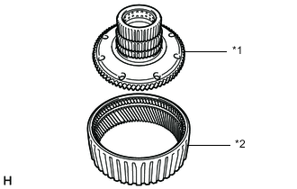
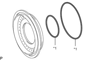
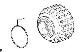
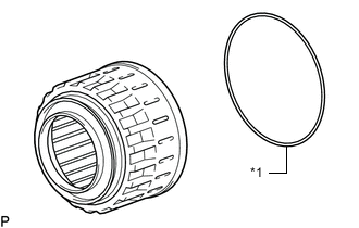
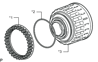
ASSEMBLE NO. 4 BRAKE PISTON AND BRAKE REACTION SLEEVE
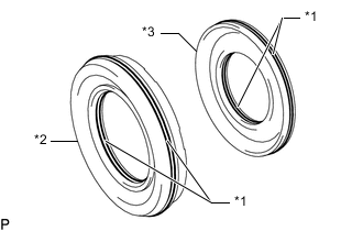
*1 O-ring *2 Brake Reaction Sleeve *3 No. 4 Brake Piston
-
Coat 2 new O-rings with ATF, and install them to the brake reaction sleeve.
-
Coat 2 new O-rings with ATF, and install them to the No. 4 brake piston.
-
Install the No. 4 brake piston to the brake reaction sleeve.
Note
Be careful not to damage the O-rings.
-
-
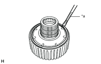
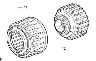
INSTALL NO. 4 BRAKE PISTON WITH BRAKE REACTION SLEEVE
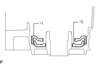
*1 Brake Reaction Sleeve *2 No. 4 Brake Piston
-
Install the No. 4 brake piston with brake reaction sleeve to the automatic transmission case sub-assembly.
Note
Be careful not to damage the O-ring.
-
-
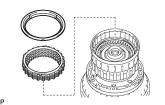
INSTALL 1ST AND REVERSE BRAKE PISTON
-
Coat a new O-ring with ATF.
-
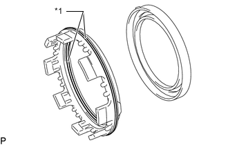
*1 1st and Reverse Brake Piston Install the O-ring to the 1st and reverse brake piston.
-
With the spring seat of the 1st and reverse brake piston facing upwards (front side), place the 1st and reverse brake piston in the automatic transmission case sub-assembly.
Note
Be careful not to damage the O-ring.
-
-
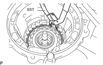
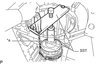
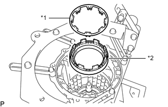
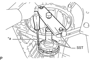
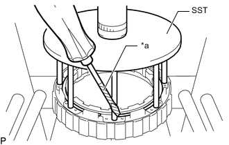
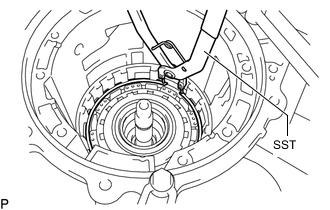
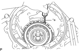
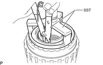
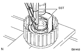
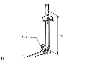
INSTALL 1ST AND REVERSE BRAKE RETURN SPRING SUB-ASSEMBLY
-
Place the 1st and reverse brake return spring sub-assembly onto the 1st and reverse brake piston.
-
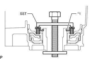
*1 Snap Ring Place SST on the 1st and reverse brake return spring sub-assembly, and compress the 1st and reverse brake return spring sub-assembly.
- SST
- 09350-30020 ( 09350-07050 )
-
Using SST, install the snap ring.
- SST
- 09350-30020 ( 09350-07070 )
-
-
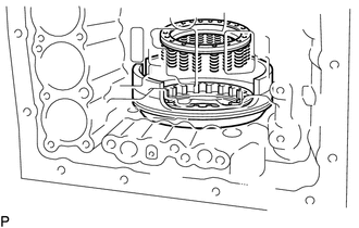
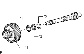
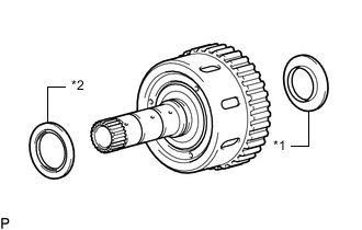
INSTALL REAR PLANETARY GEAR ASSEMBLY
-
Install the No. 9 thrust bearing race.
Thrust Bearing Race Diameter Item Inside Outside No. 9 Thrust Bearing Race
(Rear race J)
47.1 mm (1.85 in.) 67.1 mm (2.64 in.) -
*1 Thrust Needle Roller Bearing
(Thrust Bearing I)
*2 Thrust Needle Roller Bearing
(Thrust Bearing J)
Coat the 2 thrust needle roller bearings with ATF, and install them to the rear planetary gear assembly.
Thrust Needle Roller Bearing Diameter Item Inside Outside Thrust needle roller bearing
(Thrust bearing J)
43.55 mm (1.71 in.) 61.0 mm (2.40 in.) Thrust needle roller bearing
(Thrust bearing I)
21.5 mm (0.846 in.) 40.8 mm (1.61 in.) -
Install the rear planetary gear assembly.
-
-
INSPECT PACK CLEARANCE OF 1ST AND REVERSE BRAKE
-
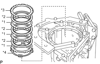
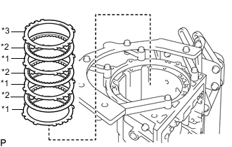
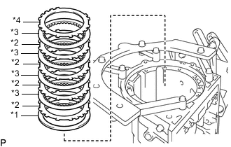
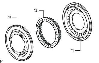
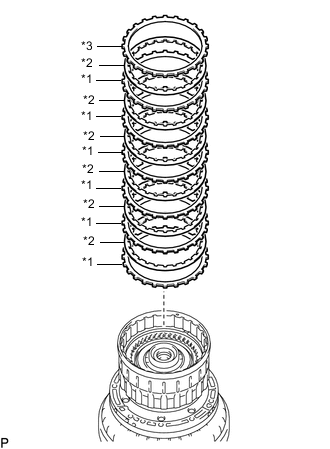
INSTALL NO. 4 BRAKE DISC
-
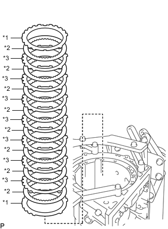
*1 No. 4 Brake Flange *2 No. 4 Brake Disc *3 No. 4 Brake Plate Install the 2 flanges, 8 discs and 7 plates.
Note
-
Make sure that the No. 4 brake discs, No. 4 brake plates and No. 4 brake flanges are installed in the correct order.
-
Install the thicker No. 4 brake flange first, and then install the thinner one.
-
-
-
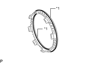
INSTALL BRAKE PLATE STOPPER SPRING
-
Install the brake plate stopper spring.
-
-
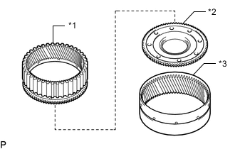
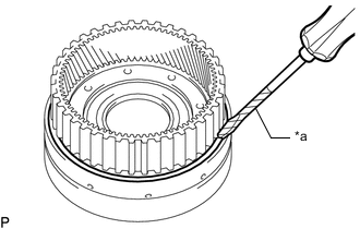
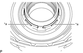
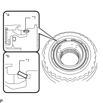
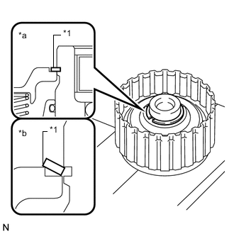
INSTALL REAR PLANETARY RING GEAR
-
*1 Rear Planetary Ring Gear Flange Sub-assembly *2 Rear Planetary Ring Gear Install the rear planetary ring gear to the rear planetary ring gear flange sub-assembly.
-
*a Protective Tape Using a screwdriver, install the snap ring to the rear planetary ring gear flange sub-assembly with rear planetary ring gear.
Note
Be careful not to damage the rear planetary ring gear flange sub-assembly with rear planetary ring gear.
Tech Tips
Tape the screwdriver tip before use.
-
-
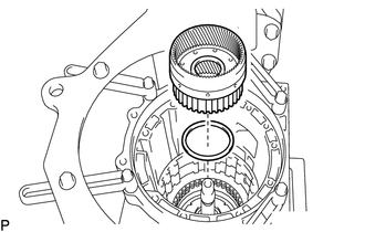
INSTALL REAR PLANETARY RING GEAR FLANGE SUB-ASSEMBLY WITH REAR PLANETARY RING GEAR
-
*1 No. 7 Thrust Bearing Race
(Front Race H)
*2 Thrust Needle Roller Bearing
(Thrust Bearing H)
*3 No. 8 Thrust Bearing Race
(Rear Race H)
*4 Rear Planetary Ring Gear Flange Sub-assembly Install the No. 8 thrust bearing race, thrust needle roller bearing, No. 7 thrust bearing race and rear planetary ring gear flange sub-assembly with the rear planetary ring gear to the intermediate shaft.
Thrust Needle Roller Bearing and Race Diameter Item Inside Outside No. 7 thrust bearing race
(Front Race H)
33.4 mm (1.31 in.) 49.0 mm (1.93 in.) Thrust needle roller bearing
(Thrust bearing H)
32.1 mm (1.26 in.) 49.35 mm (1.94 in.) No. 8 thrust bearing race
(Rear race H)
32.1 mm (1.26 in.) 49.0 mm (1.93 in.)
-
-
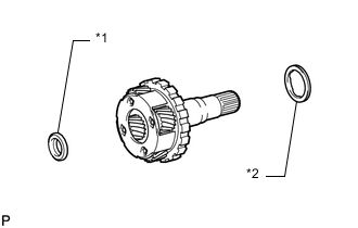
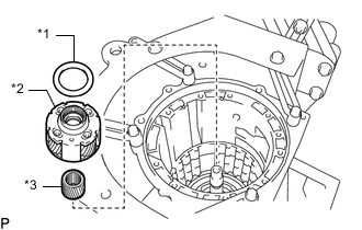
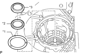
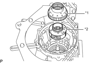
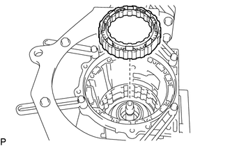
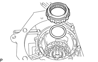
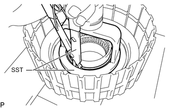
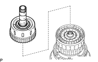
INSTALL NO. 3 ONE-WAY CLUTCH ASSEMBLY
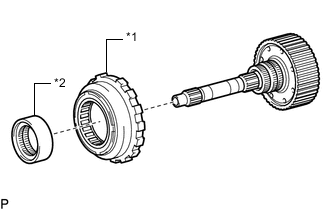
*1 No. 3 One-way Clutch Assembly *2 One-way Clutch Inner Race
-
Install the No. 3 one-way clutch assembly and one-way clutch inner race to the intermediate shaft.
-
-
INSTALL INTERMEDIATE SHAFT
-
Install the intermediate shaft with the No. 3 one-way clutch assembly to the automatic transmission case sub-assembly.
-
Using SST, install the snap ring.
- SST
- 09350-30020 ( 09350-07060 )
-
-
INSTALL CENTER PLANETARY GEAR ASSEMBLY
*1 No. 4 Thrust Bearing Race
(Rear Race G)
*2 Center Planetary Gear Assembly *3 Planetary Sun Gear
-
Install the planetary sun gear and center planetary gear to the case.
-
Coat the No. 4 thrust bearing race with ATF, and install it onto the center planetary gear assembly.
Thrust Bearing Race Diameter Item Inside Outside No. 4 thrust bearing race
(Rear race G)
53.7 mm (2.11 in.) 74.0 mm (2.91 in.)
-
-
INSTALL NO. 2 BRAKE PISTON
-
*1 O-ring Coat 2 new O-rings with ATF, and install them to the No. 2 brake piston.
-
Press the No. 2 brake piston into the No. 2 brake cylinder.
Note
Be careful not to damage the O-rings.
-
Install the No. 2 brake piston to the automatic transmission case sub-assembly.
Tech Tips
Install the No. 2 brake cylinder so that the projection protrudes from the upside of the automatic transmission case sub-assembly.
-
Check that the oil pressure apply hole of the No. 2 brake cylinder aligns with the oil pressure apply hole of the automatic transmission case sub-assembly.
-
-
INSTALL NO. 2 BRAKE DISC
*1 No. 2 Brake Plate *2 No. 2 Brake Disc *3 No. 2 Brake Flange *4 No. 2 Brake Piston Return Spring Sub-assembly
-
Install the No. 2 brake flange, 3 No. 2 brake plates, 3 No. 2 brake discs and No. 2 brake piston return spring sub-assembly.
Note
-
Make sure that the No. 2 brake piston return spring sub-assembly, No. 2 brake discs, No. 2 brake plates and No. 2 brake flanges are installed in the correct order.
-
Install the thicker No. 2 brake piston return spring sub-assembly, and then install the thinner one.
-
-
*a Protective Tape Using SST and a screwdriver, compress the No. 2 brake piston return spring sub-assembly and install the snap ring to the automatic transmission case sub-assembly.
- SST
- 09351-40010 ( 09351-04010, 09351-04020, 09351-04040, 09351-04050 )
Note
Be careful not to damage the automatic transmission case sub-assembly.
Tech Tips
Tape the screwdriver tip before use.
-
-
INSTALL NO. 1 BRAKE PISTON
*1 O-ring
-
Coat 2 new O-rings with ATF, and install them to the No. 1 brake piston.
-
Press the No. 1 brake piston into the No. 1 brake cylinder.
Note
Be careful not to damage the 2 O-rings.
-
-
INSTALL BRAKE PISTON RETURN SPRING SUB-ASSEMBLY
*1 Brake Piston Return Spring Sub-assembly *2 No. 1 Brake Cylinder
-
Install the brake piston return spring sub-assembly and the No. 1 brake piston with the No. 1 brake cylinder to the automatic transmission case sub-assembly.
-
Check that the oil pressure apply hole of the No. 1 brake cylinder aligns with the oil pressure apply hole of the automatic transmission case sub-assembly.
-
*a Protective Tape Using SST and a screwdriver, compress the brake piston return spring sub-assembly and install the snap ring to the automatic transmission case sub-assembly.
- SST
- 09351-40010 ( 09351-04010, 09351-04030, 09351-04040, 09351-04050 )
Note
Be careful not to damage the automatic transmission case sub-assembly.
Tech Tips
Tape the screwdriver tip before use.
-
-
INSTALL CENTER PLANETARY RING GEAR
-
*1 Center Planetary Ring Gear *2 Front Planetary Ring Gear Flange *3 Front Planetary Ring Gear Install the center planetary ring gear and front planetary ring gear flange on the front planetary ring gear.
-
*a Protective Tape Using a screwdriver, install the snap ring.
Note
-
Install the snap ring to the ring gear so that the both ends of the snap ring come to the center of a protrusion on the ring gear.
-
Be careful not to damage the front planetary ring gear.
Tech Tips
Tape the screwdriver tip before use.
-
-
-
INSTALL FRONT PLANETARY RING GEAR
-
Coat the thrust needle roller bearing with ATF, and install it to the front planetary ring gear flange.
Thrust Bearing Race Diameter Item Inside Outside Thrust needle roller bearing
(Thrust bearing G)
55.7 mm (2.19 in.) 76.4 mm (3.01 in.) -
Install the front planetary ring gear to the automatic transmission case sub-assembly.
-
*1 No. 2 Planetary Carrier Thrust Washer *2 Thrust Needle Roller Bearing
(Thrust Bearing F)
*3 No. 3 Thrust Bearing Race
(Front Race F)
Coat the No. 2 planetary carrier thrust washer and thrust needle roller bearing, and install them.
-
Coat the No. 3 thrust bearing race with ATF, and install it onto the front planetary ring gear.
Thrust Needle Roller Bearing and Race Diameter Item Inside Outside Thrust needle roller bearing
(Thrust bearing F)
43.4 mm (1.71 in.) 58.3 mm (2.30 in.) No. 3 thrust bearing race
(Front race F)
38.0 mm (1.50 in.) 57.0 mm (2.24 in.)
-
-
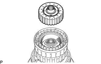
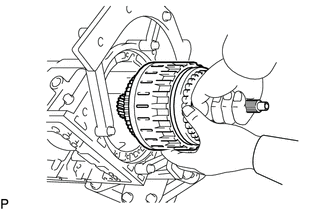
INSTALL FRONT PLANETARY GEAR ASSEMBLY
-
*1 One-way Clutch Inner Race *2 Front Planetary Gear Assembly Install the front planetary gear assembly and one-way clutch inner race to the automatic transmission case sub-assembly.
-
-
INSPECT PACK CLEARANCE OF NO. 1 BRAKE PISTON
-
INSTALL NO. 1 BRAKE DISC
*1 No. 1 Brake Plate *2 No. 1 Brake Disc *3 No. 1 Brake Flange
-
Install the 3 No. 1 brake plates, 3 No. 1 brake discs and No. 1 brake flange.
Note
-
Make sure that the No. 1 brake discs, No. 1 brake plates and No. 1 brake flange are installed in the correct order.
-
Install the thicker No. 1 brake plate, and then install the thinner one.
-
-
-
INSTALL 2ND BRAKE PISTON
-
*1 O-ring Coat 2 new O-rings with ATF, and install them to the 2nd brake piston.
-
Press the 2nd brake piston into the 2nd brake cylinder.
Note
Be careful not to damage the 2 O-rings.
-
*a Protective Tape Using SST, a screwdriver and a press, install the No. 3 brake piston return spring sub-assembly with the snap ring.
- SST
- 09351-40010 ( 09351-04060, 09351-04070 )
Note
-
Be sure that the end gap of the snap ring is not aligned with the spring retainer claw.
-
Be careful not to damage the 2nd brake cylinder.
Tech Tips
Tape the screwdriver tip before use.
-
-
INSTALL 2ND BRAKE CYLINDER
-
Install the 2nd brake cylinder to the automatic transmission case sub-assembly.
-
Check that the oil pressure apply hole of the brake cylinder aligns with the oil pressure apply hole of the automatic transmission case sub-assembly.
-
Using SST, install the snap ring.
- SST
- 09350-30020 ( 09350-07060 )
-
-
INSTALL ONE-WAY CLUTCH ASSEMBLY
-
Install the one-way clutch assembly and No. 1 planetary carrier thrust washer to the automatic transmission case sub-assembly.
-
-
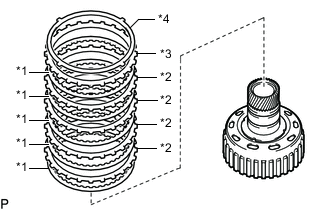
INSTALL NO. 3 BRAKE DISC
-
*1 Brake Cushion Plate *2 No. 3 Brake Plate *3 No. 3 Brake Disc *4 No. 3 Brake Flange Install the break cushion plate, 4 No. 3 brake plates, 4 No. 3 brake discs and No. 3 brake flange to the case.
Note
-
Make sure that the brake cushion plate, No. 3 brake discs, No. 3 brake plates and No. 3 brake flange are installed in the correct order.
-
Install the thicker brake cushion plate, and then install the thinner one.
-
-
*a Protective Tape Using a screwdriver, install the snap ring.
CAUTION:
Be careful not to damage the automatic transmission case sub-assembly.
Tech Tips
Tape the screwdriver tip before use.
-
-
INSTALL DIRECT CLUTCH PISTON SUB-ASSEMBLY
*1 O-ring
-
Coat 2 new O-rings with ATF, and install them in the direct clutch piston sub-assembly.
-
*1 Direct Clutch Piston Sub-assembly *2 Direct Clutch Return Spring Sub-assembly *3 No. 2 Clutch Balancer Install the No. 2 clutch balancer and direct clutch return spring sub-assembly to the direct clutch piston sub-assembly.
-
Press the direct clutch piston sub-assembly into the reverse clutch drum sub-assembly by hands.
Note
Be careful not to damage the 2 O-rings.
-
Place SST on the No. 2 clutch balancer , and compress the direct clutch return spring sub-assembly with a press.
- SST
- 09320-89010
Note
Stop pressing when the spring sheet is lowered to the place 1 to 2 mm (0.0394 to 0.0787 in.) from the snap ring groove to prevent the spring sheet from being deformed.
-
Using SST, install the snap ring.
- SST
- 09350-30020 ( 09350-07070 )
Note
-
Be sure that the end gap of the snap ring is not aligned with the spring retainer claw.
-
Do not expand the snap ring excessively.
-
*a Stopper Install the snap ring so that the outside line fits against the stopper of the No. 2 clutch balancer as shown in the illustration.
-
-
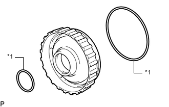
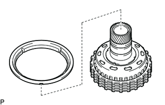
INSTALL REVERSE CLUTCH PISTON SUB-ASSEMBLY
-
*1 O-ring Coat a new O-ring with ATF, and install it to the reverse clutch drum sub-assembly.
-
*1 O-ring Coat a new O-ring with ATF, and install it to the reverse clutch piston sub-assembly.
-
*1 Reverse Clutch Piston Sub-assembly *2 Clutch Drum Press the clutch drum into the reverse clutch piston sub-assembly with both hands.
Note
Do not damage the O-rings.
-
-
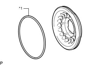
INSTALL REVERSE CLUTCH RETURN SPRING SUB-ASSEMBLY
-
*1 Reverse Clutch Return Spring Sub-assembly *2 O-ring *3 Reverse Clutch Piston Sub-assembly Coat a new O-ring with ATF, and install it to the reverse clutch piston sub-assembly.
-
Install the reverse clutch return spring sub-assembly onto the reverse clutch piston sub-assembly.
-
-
INSTALL NO. 3 CLUTCH BALANCER
-
Install the No. 3 clutch balancer to the reverse clutch return spring sub-assembly.
-
Place SST on the No. 3 clutch balancer, and compress the No. 3 clutch balancer with a press.
- SST
- 09387-00070
Note
Stop pressing when the spring sheet is lowered to the place 1 to 2 mm (0.0394 to 0.0787 in.) from the snap ring groove to prevent the spring sheet from being deformed.
-
Using SST, install the snap ring.
- SST
- 09350-30020 ( 09350-07070 )
Note
-
Be sure that the end gap of the snap ring is not aligned with the spring retainer claw.
-
Do not expand the snap ring excessively.
-
*1 Snap Ring *a Correct *b Incorrect Set the end gap of the snap ring in the piston as shown in the illustration.
Note
Be sure the end gap of the snap ring is not aligned with the spring retainer claw.
-
-
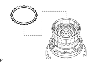
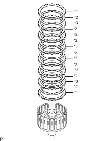
INSTALL DIRECT CLUTCH DISC
-
*1 Clutch Plate *2 Direct Clutch Disc *3 Direct Clutch Flange Install the 6 clutch plates, 6 direct clutch discs and direct clutch flange to the clutch drum.
Install in order *1 - *2 - *1 - *2 - *1 - *2 - *1 - *2 - *1 - *2 - *1 - *2 - *3 Note
-
Make sure that the clutch plates, direct clutch discs and direct clutch flange are installed in the correct order.
-
Install the clutch plate, and then install the thinner one.
-
-
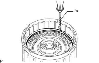
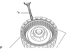
*a Protective Tape Using a screwdriver, install the 2 snap rings on the clutch drum.
Note
Be careful not to damage the clutch drum.
Tech Tips
Tape the screwdriver tip before use.
-
-
INSPECT PACK CLEARANCE OF DIRECT CLUTCH
-
INSTALL REVERSE CLUTCH FLANGE
-
Install the reverse clutch flange to the clutch drum.
Note
Install the flange that is 3 mm thick.
-
-
INSTALL REVERSE CLUTCH REACTION SLEEVE
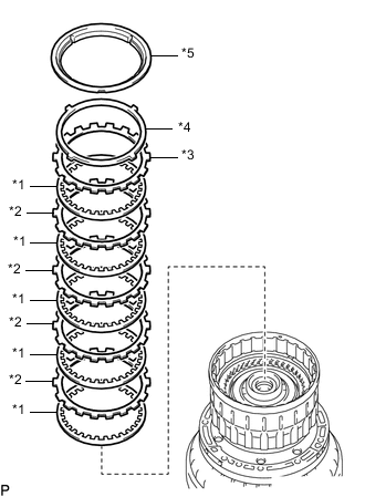
*1 Reverse Clutch Disc *2 Clutch Plate *3 Reverse Clutch Flange *4 Clutch Cushion Plate *5 Reverse Clutch Reaction Sleeve
-
Install the 5 reverse clutch discs, 4 clutch plates, reverse clutch flange, clutch cushion plate and reverse clutch reaction sleeve to the reverse clutch piston sub-assembly.
Install in order *1 - *2 - *1 - *2 - *1 - *2 - *1 - *2 - *1 - *3 - *4 - *5 Note
-
Make sure that the reverse clutch discs, clutch plates, reverse clutch flange, clutch cushion plate and reverse clutch reaction sleeve are installed in the correct order.
-
Install the reverse clutch disc, and then install the thinner one.
-
-
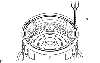
Using a screwdriver, install the snap ring.
Note
Be careful not to damage the reverse clutch piston sub-assembly.
Tech Tips
Tape the screwdriver tip before use.
-
-
INSPECT PACK CLEARANCE OF REVERSE CLUTCH
-
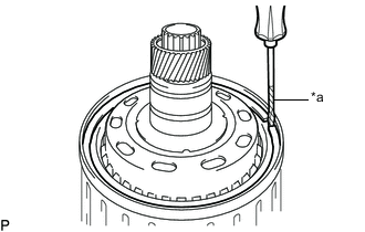
REMOVE REVERSE CLUTCH REACTION SLEEVE
*a Protective Tape
-
Using a screwdriver, remove the snap ring from the clutch drum.
Note
Be careful not to damage the reverse clutch drum sub-assembly and reverse clutch sleeve.
Tech Tips
Tape the screwdriver tip before use.
-
Remove the reverse clutch reaction sleeve, clutch cushion plate, reverse clutch flange, 5 reverse clutch discs, and 4 clutch plates from the reverse clutch piston sub-assembly.
-
-
INSTALL FORWARD CLUTCH PISTON
*1 O-ring
-
Coat 2 new O-rings with ATF, and install them to the forward clutch piston.
-
Install the forward clutch piston to the input shaft assembly.
Note
Be careful not to damage the 2 O-rings.
-
-
INSTALL NO. 1 CLUTCH BALANCER
*1 O-ring
-
Coat a new O-ring with ATF and install it to the clutch balancer.
-
*1 No. 1 Clutch Balancer *2 Forward Clutch Return Spring Sub-assembly Install the No. 1 clutch balancer and forward clutch return spring assembly.
Note
Be careful not to damage the O-ring.
-
Place SST on the No. 1 clutch balancer, and compress the return spring assembly with a press.
- SST
- 09350-30020 ( 09350-07040 )
Note
Stop pressing when the spring sheet is lowered to a position 1 to 2 mm (0.0393 to 0.0787 in.) from the snap ring groove to prevent the spring sheet from being deformed.
-
Using SST, install the snap ring.
- SST
- 09350-30020 ( 09350-07070 )
Note
Do not expand the snap ring excessively.
-
*1 Snap Ring *a Correct *b Incorrect Set the end gap of the snap ring in the No. 1 clutch balancer as shown in the illustration.
-
-
INSTALL FORWARD MULTIPLE DISC CLUTCH DISC
-
*1 Forward Clutch Flange *2 Forward Multiple Disc Clutch Disc *3 Clutch Plate Install the 2 forward clutch flanges, 7 forward multiple disc clutch discs and 6 clutch plates to the input shaft assembly.
Note
-
Make sure that the forward clutch flanges, forward multiple disc clutch discs and clutch plates are installed in the correct order.
-
Install the forward clutch flange, and then install the thinner one.
-
If the forward clutch flanges have different thicknesses, first install the thinner flange.
-
-
*a Protective Tape Using a screwdriver, install the snap ring.
Note
Be careful not to damage the input shaft.
Tech Tips
Tape the screwdriver tip before use.
-
-
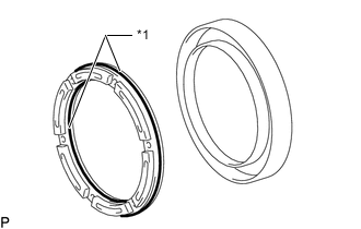
INSTALL INPUT SHAFT OIL SEAL RING
-
Coat 3 new input shaft oil seal rings with ATF.
-
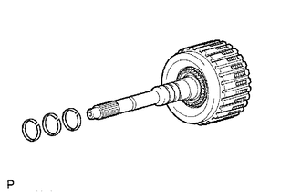
Squeeze the ends of the 3 input shaft oil seal rings together, and then install them to the input shaft groove.
Note
Do not excessively widen the input shaft oil seal ring.
Tech Tips
After installing the input shaft oil seal rings, check that they rotate smoothly.
-
-
INSPECT PACK CLEARANCE OF FORWARD CLUTCH
-
INSTALL INPUT SHAFT ASSEMBLY
-
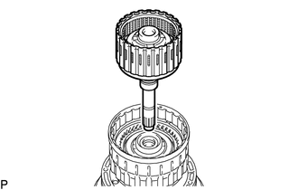
Install the input shaft assembly to the clutch drum.
-
Coat the thrust needle roller bearing with ATF and Install it to the clutch drum.
Thrust Needle Roller Bearing Diameter Item Inside Outside Thrust needle roller bearing
(Thrust bearing C)
21.3 mm (0.839 in.) 41.1 mm (1.62 in.)
-
-
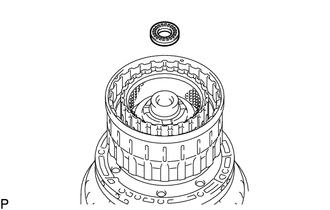
INSTALL MULTIPLE DISC CLUTCH HUB
-
*1 No. 3 Thrust Bearing Race
(Rear Race C)
*2 No. 4 Thrust Bearing Race
(Front Race D)
Coat the No. 3 thrust bearing race and No. 4 thrust bearing race with ATF and install them to the multiple disc clutch hub.
Thrust Bearing Race Diameter Item Inside Outside No. 3 thrust bearing race
(Rear race C)
22.6 mm (0.890 in.) 45.0 mm (1.77 in.) No. 4 thrust bearing race
(Front race D)
38.4 mm (1.51 in.) 56.5 mm (2.22 in.) -
Install the multiple disc clutch hub to the reverse clutch piston sub-assembly.
-
-
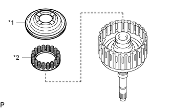
INSTALL FORWARD CLUTCH HUB SUB-ASSEMBLY
-
*1 Thrust Needle Roller Bearing
(Thrust Bearing D)
*2 Thrust Needle Roller Bearing
(Thrust Bearing E)
Coat the 2 thrust needle roller bearings with ATF, and install them to the forward clutch hub sub-assembly.
Thrust Needle Roller Bearing Diameter Item Inside Outside Thrust needle roller bearing
(Thrust bearing D)
33.3 mm (1.31 in.) 51.5 mm (2.02 in.) Thrust needle roller bearing
(Thrust bearing E)
42.5 mm (1.67 in.) 61.2 mm (2.41 in.) -
Install the forward clutch hub sub-assembly to the reverse clutch piston sub-assembly.
-
-
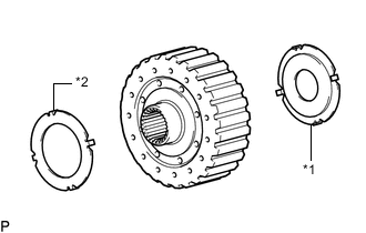
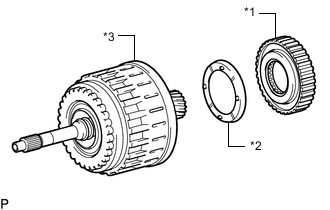
INSTALL REVERSE CLUTCH DISC
-
*1 Reverse Clutch Disc *2 Clutch Plate *3 Reverse Clutch Flange *4 Clutch Cushion Plate Install the 5 reverse clutch discs, 4 clutch plates, reverse clutch flange and clutch cushion plate to the reverse clutch hub sub-assembly.
Note
-
Make sure that the reverse clutch discs, clutch plates, reverse clutch flange and clutch cushion plate are installed in the correct order.
-
-
-
INSTALL REVERSE CLUTCH REACTION SLEEVE
-
Install the reverse clutch reaction sleeve to the reverse clutch hub sub-assembly.
-
-
INSTALL REVERSE CLUTCH HUB SUB-ASSEMBLY
-
Install the reverse clutch hub sub-assembly to the reverse clutch piston sub-assembly.
-
*a Protective Tape Using a screwdriver, install the snap ring to the clutch drum and input shaft assembly.
Note
Be careful not to damage the reverse clutch piston sub-assembly.
Tech Tips
Tape the screwdriver tip before use.
-
-
INSTALL NO. 2 ONE-WAY CLUTCH ASSEMBLY
-
*1 No. 2 One-way Clutch Assembly *2 No. 2 Clutch Drum Thrust Washer *3 Reverse Clutch Piston sub-assembly Install the No. 2 one-way clutch assembly and No. 2 clutch drum thrust washer to the reverse clutch piston sub-assembly.
Note
Be sure to install the No. 2 clutch drum thrust washer in the correct direction.
-
-
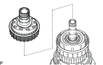
INSTALL CLUTCH DRUM AND INPUT SHAFT ASSEMBLY
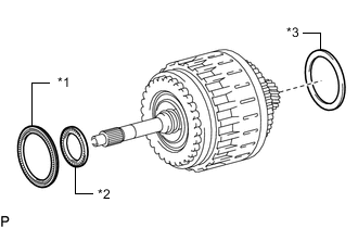
*1 Thrust Needle Roller Bearing
(Thrust Bearing A)
*2 Thrust Needle Roller Bearing
(Thrust Bearing B)
*3 Clutch Drum Thrust Washer
-
Coat the 2 thrust needle roller bearings and clutch drum thrust washer with ATF and install them to the reverse clutch piston sub-assembly.
Thrust Needle Roller Bearing Diameter Item Inside Outside Thrust needle roller bearing
(Thrust bearing A)
71.9 mm (2.83 in.) 85.6 mm (3.37 in.) Thrust needle roller bearing
(Thrust bearing B)
34.6 mm (1.36 in.) 52.0 mm (2.05 in.) -
Install the reverse clutch piston sub-assembly to the automatic transmission case sub-assembly.
-
-
INSTALL OIL PUMP ASSEMBLY
*1 No. 1 Thrust Bearing Race
(Front Race A)
*2 No. 2 Thrust Bearing Race
(Front Race B)
-
Coat the No. 1 thrust bearing race and No. 2 thrust bearing race with ATF, and install them to the oil pump assembly.
Thrust Bearing Race Diameter Item Inside Outside No. 1 thrust bearing race
(Front race A)
74.2 mm (2.92 in.) 87.74 mm (3.45 in.) No. 2 Thrust bearing race
(Front race B)
37.0 mm (1.46 in.) 52.3 mm (2.06 in.) -
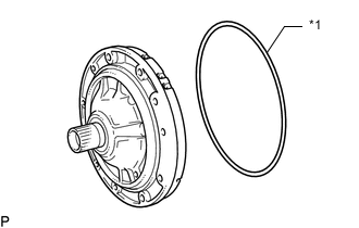
*1 O-ring Coat a new O-ring with ATF, and install it to the oil pump assembly.
-
Clean the bolt and the bolt hole.
-
Place the oil pump assembly through the input shaft, and align the bolt holes of the oil pump assembly with the automatic transmission case sub-assembly.
-
Hold the input shaft assembly, and lightly press the oil pump assembly to slide the input shaft oil seal rings into the reverse clutch piston sub-assembly.
Note
Do not excessively push on the oil pump assembly, as the input shaft oil seal ring will stick to the clutch drum.
-
Apply adhesive to 2 or 3 threads on the end of the 10 bolts.
Adhesive Toyota Genuine Adhesive 1344, Three Bond 1344 or equivalent -
Install the 10 bolts.
- Torque:
- 21 N*m { 214 kgf*cm, 15 ft.*lbf }
-
-
INSTALL MANUAL VALVE LEVER SHAFT OIL SEAL
-
Coat the manual valve lever shaft oil seal lips with MP grease.
-
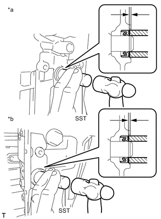
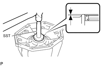
*a RH Side *b LH Side Using SST and a hammer, drive in 2 new manual valve lever shaft oil seals.
- SST
- 09350-30020 ( 09350-07110 )
Oil seal drive in depth -0.3 to 0.3 mm (-0.0118 to 0.0118 in.)
-
-
INSPECT INDIVIDUAL PISTON OPERATION
-
INSTALL MANUAL VALVE LEVER SUB-ASSEMBLY
*1 Spacer *2 Manual Valve Lever Sub-assembly
-
Install a new spacer to the manual valve lever sub-assembly.
-
Push the manual valve lever shaft through the automatic transmission case sub-assembly, and install the manual valve lever sub-assembly to the manual valve lever shaft.
-
Using a hammer, tap in a new spring pin.
-
Align the manual valve lever indentation with the spacer hole, and stake them together with a punch.
-
Check that the shaft rotates smoothly.
-
-
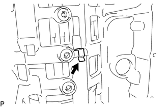
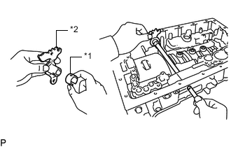
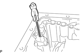
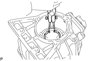
INSTALL PARKING LOCK PAWL SHAFT
*1 Parking Lock Pawl *2 E-ring *3 Parking Lock Pawl Shaft *4 Spring
-
Install a new E-ring to the shaft.
-
Install the parking lock pawl, parking lock pawl shaft and spring.
-
-
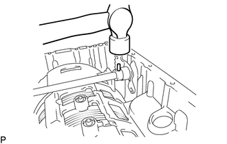
INSTALL PARKING LOCK ROD SUB-ASSEMBLY
-
Connect the parking lock rod sub-assembly to the manual valve lever sub-assembly as shown in the illustration.
-
-
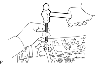
INSTALL PARKING LOCK PAWL BRACKET
-
Place the parking lock pawl bracket onto the automatic transmission case sub-assembly and tighten the 3 bolts.
- Torque:
- 7.4 N*m { 75 kgf*cm, 65 in.*lbf }
-
*1 Manual Valve Lever Sub-assembly *2 Planetary Ring Gear *3 Parking Lock Pawl Shift the manual valve lever sub-assembly to the P, and confirm that the planetary gear is correctly locked up by the parking lock pawl.
-
-
INSTALL C-1 ACCUMULATOR VALVE
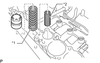
*1 Outer Spring *2 Inner Spring
-
Install the 2 springs and C-1 accumulator valve to the hole.
C-1 Accumulator Spring Inner Spring Free Length Outer Diameter Color 30.40 mm (1.20 in.) 11.40 mm (0.449 in.) Pink Outer Spring Free Length Outer Diameter Color 48.76 mm (1.92 in.) 16.60 mm (0.654 in.) Light green
-
-
INSTALL C-3 ACCUMULATOR PISTON
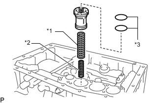
*1 Outer Spring *2 Inner Spring *3 O-ring
-
Coat 2 new O-rings with ATF, and install them to the C-3 accumulator piston.
-
Install the 2 springs and C-3 accumulator piston to the hole.
C-3 Accumulator Spring Inner Spring Free Length Outer Diameter Color 44.0 mm (1.73 in.) 14.0 mm (0.551 in.) Yellow Outer Spring Free Length Outer Diameter Color 73.35 mm (2.89 in.) 19.90 mm (0.783 in.) Red
-
-
INSTALL B-3 ACCUMULATOR PISTON
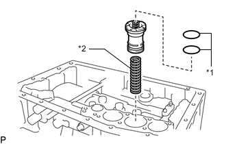
*1 O-ring *2 Spring
-
Coat 2 new O-rings with ATF, and install them to the piston.
-
Install the spring and B-3 accumulator piston to the hole.
B-3 Accumulator Spring Free Length Outer Diameter Color 70.5 mm (2.78 in.) 19.7 mm (0.776 in.) Purple
-
-
INSTALL C-2 ACCUMULATOR PISTON
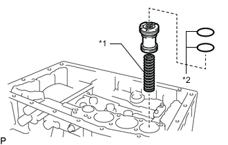
*1 Spring *2 O-ring
-
Coat 2 new O-rings with ATF, and install them to the piston.
-
Install the spring and C-2 accumulator piston to the hole.
C-2 Accumulator Spring Free Length Outer Diameter Color 62.0 mm (2.44 in.) 15.9 mm (0.626 in.) White
-
-
INSTALL CHECK BALL BODY
-
Install the spring and check ball body.
-
-
INSTALL BRAKE DRUM GASKET
-
Install a new 3 brake drum gaskets.
-
-
INSTALL TRANSMISSION CASE GASKET
-
Coat 3 new transmission case gaskets with ATF, and install the transmission case gaskets.
-
-
INSTALL TRANSMISSION VALVE BODY ASSEMBLY
-
INSTALL TRANSMISSION WIRE
-
INSTALL VALVE BODY OIL STRAINER ASSEMBLY
-
INSTALL AUTOMATIC TRANSMISSION OIL PAN SUB-ASSEMBLY
-
Install the automatic transmission oil pan sub-assembly.
-
Install a new gasket and the drain plug.
- Torque:
- 20 N*m { 204 kgf*cm, 15 ft.*lbf }
-
Install a new gasket and the overflow plug.
- Torque:
- 20 N*m { 204 kgf*cm, 15 ft.*lbf }
-
-
INSTALL REAR TRANSFER CASE ADAPTER OIL RECEIVER
-
Install the transfer case adapter oil receiver to the rear transfer adaptor.
-
Using snap ring pliers, install the snap ring.
-
-
INSTALL TRANSFER ADAPTER OIL SEAL
-
Coat the lip of a new transfer adapter oil seal with MP grease.
-
Using SST and a hammer, tap in a new transfer adapter oil seal.
- SST
- 09950-60010 ( 09951-00650 )
- 09950-70010 ( 09951-07150 )
Standard depth 0 to 0.5 mm (0 to 0.0196 in.)
-
-
INSTALL TRANSFER ADAPTER SUB-ASSEMBLY
-
Clean the threads of the bolts and the automatic transmission case sub-assembly and transfer adapter sub-assembly with non-residue solvent.
Note
Using a razor blade and gasket scraper, remove all the old seal packing material from the gasket surfaces.
-
*a Seal Packing Apply seal packing to the transfer adapter sub-assembly as shown in the illustration.
Seal packing Toyota Genuine Seal Packing 1281, Three Bond 1281 or equivalent Note
-
Apply seal packing in a continuous line (width approximately 1.2 mm (0.0472 in.)) along the sealing surface.
-
Parts must be assembled within 10 minutes of application. Otherwise, the seal packing material must be removed and reapplied.
-
-
Apply a few drops of adhesive to 2 or 3 threads of each of the 8 bolts.
Adhesive Toyota Genuine Adhesive 1344, Three Bond 1344 or Equivalent -
Install the extension housing sub-assembly with 8 bolts.
- Torque:
- 33.9 N*m { 346 kgf*cm, 25 ft.*lbf }
Bolt Length Item Length Bolt A 40 mm (1.57 in.) Bolt B 50 mm (1.97 in.)
-
-
INSTALL AUTOMATIC TRANSMISSION HOUSING
-
Clean the threads of the bolts and the case with non-residue solvent.
-
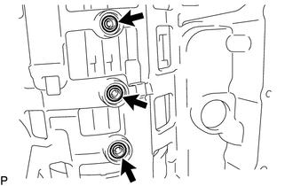
Install the automatic transmission housing to the automatic transmission case sub-assembly with the 6 bolts.
- Torque:
- 33.9 N*m { 346 kgf*cm, 25 ft.*lbf }
-
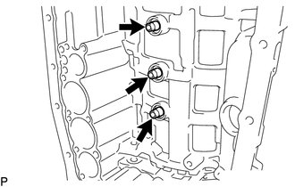
Apply a few drops of adhesive to 2 or 3 threads of each of the 4 bolts.
Adhesive Toyota Genuine Adhesive 1344, Three Bond 1344 or Equivalent -
Install the 4 bolts to the automatic transmission housing.
- Torque:
- for Bolt A (14 mm head)
- 33.9 N*m { 346 kgf*cm, 25 ft.*lbf }
- for Bolt B (17 mm head)
- 56.8 N*m { 579 kgf*cm, 42 ft.*lbf }
-
-
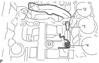
INSTALL AUTOMATIC TRANSMISSION BREATHER TUBE
-
*1 No. 1 Breather Plug *2 Automatic Transmission Breather Hose *3 Automatic Transmission Breather Tube *4 O-ring Coat a new O-ring with ATF and install it to the automatic transmission breather tube.
-
Install the No. 1 breather plug and automatic transmission breather hose to the automatic transmission breather tube.
-
Install the automatic transmission breather tube with the 2 bolts.
- Torque:
- 5.4 N*m { 55 kgf*cm, 48 in.*lbf }
-
-
INSTALL TRANSMISSION REVOLUTION SENSOR (SP2)
-
INSTALL TRANSMISSION REVOLUTION SENSOR (NT)
-
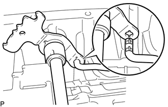
INSTALL OIL COOLER TUBE UNION
-
Coat the 2 new O-rings with ATF, and install it to 2 oil cooler tube unions.
-
*a -18 to -22° Temporarily install the 2 oil cooler tube unions as shown in the illustration.
-
*a Torque Wrench Fulcrum Length *b Hold Using a SST, hold the oil cooler tube union and tighten the 2 oil cooler tube unions.
- SST
- 09268-78010
Specified tightening torque 29.4 N*m (300 kgf*cm, 22 ft.*lbf) Tech Tips
-
Calculate the torque wrench reading when changing the fulcrum length of the torque wrench.
-
When using SST (fulcrum length of 34.5 mm (1.36 in.)) + torque wrench (fulcrum length of 300 mm (11.8 in.)): 26.4 N*m (269 kgf*cm, 19 ft.*lbf)
Note
After tightening, check that the oil cooler tube union does not move.
-
-
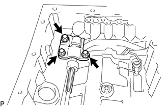
INSTALL PARK/NEUTRAL POSITION SWITCH ASSEMBLY
Tech Tips
Make sure that the manual valve lever shaft has not been rotated prior to installing the park/neutral position switch as the detent spring may become detached from the manual valve lever shaft.
-
Clean the bolt and the bolt hole.
-
Apply adhesive to 2 or 3 threads on the end of the bolt.
Adhesive Toyota Genuine Adhesive 1344, Three Bond 1344 or equivalent -
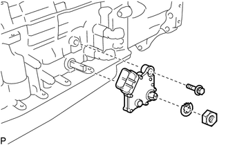
Temporarily install the park/neutral position switch assembly to the automatic transmission case sub-assembly with the bolt.
-
Install the lock washer. Install and tighten the nut.
- Torque:
- 6.9 N*m { 70 kgf*cm, 61 in.*lbf }
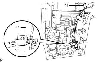
-
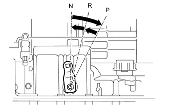
Using the transmission control shaft lever LH, turn the manual lever shaft clockwise until it stops, and then turn it counterclockwise 2 notches to set it to N.
-
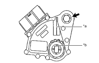
*a Neutral Basic Line *b Groove Align the neutral basic line with the switch groove, and tighten the adjusting bolt.
- Torque:
- 12.8 N*m { 131 kgf*cm, 9 ft.*lbf }
-
Using a screwdriver, bend the tabs of the lock washer.
Tech Tips
Bend at least 2 of the lock washer tabs.
-
-
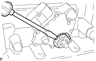
INSTALL TRANSMISSION CONTROL SHAFT LEVER LH
-
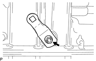
Install the transmission control shaft lever LH with the spring washer and nut.
- Torque:
- 15.7 N*m { 160 kgf*cm, 12 ft.*lbf }
-