AUTOMATIC TRANSMISSION SYSTEM ECU Power Source Circuit
DESCRIPTION
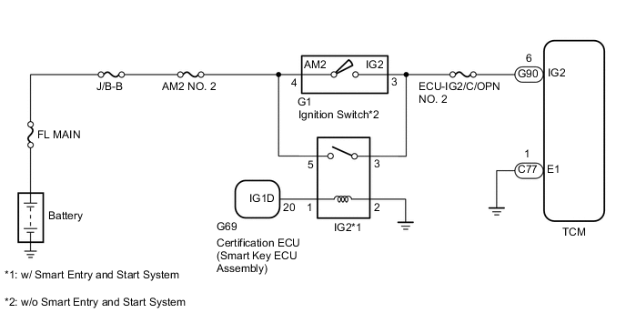
When the ignition switch is turned to ON, battery voltage is applied to terminal IG2 of the TCM.
WIRING DIAGRAM
CAUTION / NOTICE / HINT
Note
Inspect the fuses for circuits related to this system before performing the following procedure.
PROCEDURE
-
CHECK HARNESS AND CONNECTOR (TCM - BODY GROUND)
-
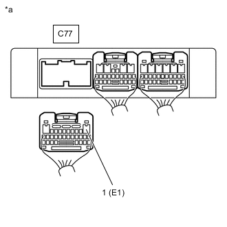
*a Rear view of wire harness connector
(to TCM)
Disconnect the TCM connector.
-
Measure the resistance according to the value(s) in the table below.
Standard Resistance Tester Connection Condition Specified Condition C77-1 (E1) - Body ground Always Below 1 Ω Result Proceed to OK NG
NG 
REPAIR OR REPLACE HARNESS OR CONNECTOR
OK 
-
-
CHECK TCM (TCM - BATTERY)
-
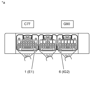
*a Rear view of wire harness connector
(to TCM)
Turn the ignition switch to ON.
-
Measure the voltage according to the value(s) in the table below.
Standard Voltage Tester Connection Switch Condition Specified Condition G90-6 (IG2) - C77-1 (E1) Ignition switch ON 11 to 14 V Result Result Proceed to OK A NG (w/o Entry and Start System) B NG (w/ Entry and Start System) C
A
REPLACE TCM Click here
C 
INSPECT IG2 RELAY Click here
B
-
-
INSPECT IGNITION SWITCH ASSEMBLY
-
Inspect the ignition switch assembly.
Result Proceed to OK NG
OK
REPAIR OR REPLACE HARNESS OR CONNECTOR (BATTERY - IGNITION SWITCH ASSEMBLY, IGNITION SWITCH ASSEMBLY - TCM)
NG
REPLACE IGNITION SWITCH ASSEMBLY Click here
-
-
INSPECT IG2 RELAY
-
Inspect the IG2 relay.
Result Proceed to OK NG
NG
REPLACE IG2 RELAY
OK
-
-
CHECK HARNESS AND CONNECTOR (NO. 4 INSTRUMENT PANEL RELAY BLOCK ASSEMBLY - TCM)
-
Remove the IG2 relay from the No. 4 instrument panel relay block assembly.
-
Disconnect the G90 TCM connector.
-
Measure the resistance according to the value(s) in the table below.
Standard Resistance Tester Connection Condition Specified Condition IG2 relay terminal 3 - G90-6 (IG2) Always Below 1 Ω IG2 relay terminal 3 or G90-6 (IG2) - Body ground and other terminals Always 10 kΩ or higher Result Proceed to OK NG
NG
REPAIR OR REPLACE HARNESS OR CONNECTOR
OK
-
-
CHECK TERMINAL VOLTAGE (IG2 RELAY)
-
Remove the IG2 relay from the No. 4 instrument panel relay block assembly.
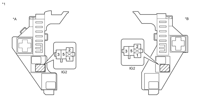
*A for RHD *B for LHD *1 No. 4 Instrument Panel Relay Block Assembly - - -
Measure the voltage according to the value(s) in the table below.
Standard Voltage Tester Connection Switch Condition Specified Condition IG2 relay terminal 5 - Body ground Always 11 to 14 V Result Proceed to OK NG
NG
REPAIR OR REPLACE HARNESS OR CONNECTOR (BATTERY - NO. 4 INSTRUMENT PANEL RELAY BLOCK ASSEMBLY)
OK
-
-
CHECK HARNESS AND CONNECTOR (CERTIFICATION ECU - NO. 4 INSTRUMENT PANEL RELAY BLOCK ASSEMBLY - BODY GROUND)
-
Disconnect the G69 certification ECU (smart key ECU assembly) connector.
-
Remove the IG2 relay from the No. 4 instrument panel relay block assembly.
-
Measure the resistance according to the value(s) in the table below.
Standard Resistance Tester Connection Condition Specified Condition G69-20 (IG1D) - IG2 Relay terminal 1 Always Below 1 Ω IG2 Relay terminal 2 - Body ground Always Below 1 Ω G69-20 (IG1D) or IG2 Relay terminal 1 - Body ground and other terminals Always 10 kΩ or higher Result Proceed to OK NG
OK
REPLACE CERTIFICATION ECU (SMART KEY ECU ASSEMBLY)
NG
REPAIR OR REPLACE HARNESS OR CONNECTOR
-