AUTOMATIC TRANSMISSION SYSTEM, Diagnostic DTC:P0560

| DTC Code | DTC Name |
|---|---|
| P0560 | System Voltage |
DESCRIPTION
The battery supplies power to the TCM even when the ignition switch is off. This power allows the TCM to store data such as DTC history and freeze frame data. If the battery voltage falls below a minimum level, the TCM data is cleared and the TCM determines that there is a malfunction in the power supply circuit. The next time the engine is started, the TCM will illuminate the MIL and store the DTC.
| DTC No. | Detection Item | DTC Detection Condition | Trouble Area | MIL | Memory |
|---|---|---|---|---|---|
| P0560 | System Voltage | TCM back-up power source circuit is low voltage for 3 seconds or more (1-trip detection logic). |
|
Comes on | DTC stored |
Tech Tips
If DTC P0560 is stored, the TCM does not store other DTCs.
WIRING DIAGRAM
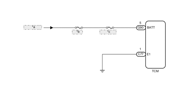
| *a | from Battery |
| *b | FL MAIN |
| *c | ECU-B NO. 3 |
CAUTION / NOTICE / HINT
Note
Inspect the fuses for circuits related to this system before performing the following procedure.
Tech Tips
After the repair, clear the DTCs and perform the following procedure to check that DTCs are not output.
-
Turn the ignition switch to ON and wait for 3 seconds or more.
-
Check for DTCs again.
PROCEDURE
-
CHECK DTC OUTPUT (ECD SYSTEM DTC P0560)
-
Connect the GTS to the DLC3.
-
Turn the ignition switch to ON.
-
Turn the GTS on.
-
Enter the following menus: Powertrain / Engine / Trouble Codes.
Powertrain > Engine > Trouble Codes -
Read the DTCs using the GTS.
Result Result Proceed to DTCs are not output A P0560 is output (ECD system) B
B 
GO TO ECD SYSTEM (DTC P0560) Click here
A 
-
-
CHECK TCM (BATTERY, GROUND)
-
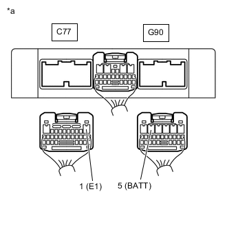
*a Rear view of wire harness connector
(to TCM)
Disconnect the TCM connectors.
-
Measure the voltage according to the value(s) in the table below.
Standard Voltage Tester Connection Condition Specified Condition G90-5 (BATT) - C77-1 (E1) Always 11 to 14 V -
Measure the resistance according to the value(s) in the table below.
Standard Resistance Tester Connection Condition Specified Condition C77-1 (E1) - Body ground Always Below 1 Ω Result Proceed to OK NG
OK
REPLACE TCM Click here
NG
REPAIR OR REPLACE HARNESS OR CONNECTOR (TCM - BATTERY, GROUND)
-