STOP AND START SYSTEM, Diagnostic DTC:P2796
| DTC Code | DTC Name |
|---|---|
| P2796 | Electromagnetic Oil Pump Circuit |
DESCRIPTION
The electromagnetic oil pump is installed inside the automatic transmission assembly.
The electromagnetic oil pump operates from the time the engine is stopped due to stop and start control until the vehicle starts moving again in order to ensure oil pressure within the automatic transmission assembly and allow for a smooth start-off.
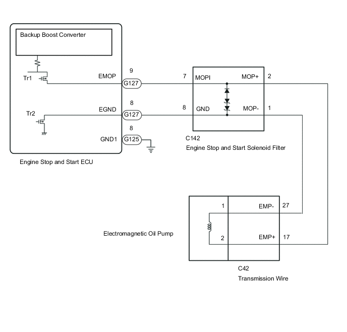
The engine stop and start ECU supplies power from the backup boost converter to the electromagnetic oil pump through Tr1 and performs Tr2 duty control to operate the electromagnetic oil pump.
The engine stop and start ECU performs Tr1 and Tr2 control when operating or not operating the electromagnetic oil pump and during the preliminary check, and also monitors the EGND terminal to record DTCs.
As a preliminary check, the first time the vehicle speed reaches 2 km/h (1.2 mph) or more on each trip and every time the vehicle speed reaches 2km/h (1.2 mph) or more after stop and start control is performed, the engine stop and start ECU turns Tr1 ON and checks that there are no malfunctions in the electromagnetic oil pump circuit.
The engine stop and start solenoid filter absorbs high-voltage counter-electromotive force generated when the electromagnetic oil pump operates.
| DTC No. | Detection Item | DTC Detection Condition | Trouble Area | Warning Indicate | Memory |
|---|---|---|---|---|---|
| P2796 | Electromagnetic Oil Pump Circuit |
|
|
Blinks | DTC stored |
CONFIRMATION DRIVING PATTERN
Tech Tips
DTCs for the stop and start system are not cleared even if the malfunction has been repaired. After repairing the malfunction, be sure to clear the DTCs.
-
Tech Tips
-
If the cable is disconnected from the battery terminal, stop and start control is prohibited until refresh charge is completed.
In this case, let the vehicle idle with the battery temperature at 11°C (51°F) or higher for 5 to 60 minutes to complete the refresh charge. (The refresh charge is complete when the Data List item Status of Battery Charge Control changes from "Refresh Charge Mode".)
-
If the GTS is not available and the Data List item Status of Battery Charge Control cannot be checked, charge the battery by idling the engine for approximately 5 to 60 minutes or driving the vehicle, and then drive the vehicle and check that stop and start control operates.
If the engine is started with the hood open, the system determines that a jump start has occurred. Therefore, make sure that the hood is closed before starting the engine and driving the vehicle.
-
After the refresh charge completes, turn the engine switch off, wait for at least 30 seconds, and then start the engine again.
If the vehicle enters refresh charge mode again while the engine is idling, the initial refresh charge did not properly complete, so wait for the refresh charge to complete.
-
Allow the engine to idle for 3 minutes after the engine warms up and check that the engine speed is within 50 rpm of the target idle speed.
CONFIRMATION AFTER TROUBLESHOOTING
-
Connect the GTS to the DLC3.
-
Turn the ignition switch to ON and turn the GTS on.
-
Clear the DTCs.
-
Start the engine and warm it up.
-
Drive the vehicle at 7 km/h (4.3 mph) or more.
CAUTION:
When performing Confirmation Driving Pattern, obey all speed limits and traffic laws.
-
Depress the brake pedal and stop the vehicle.
-
Keep the engine stopped by stop and start control. (Keep the shift lever in D.)
-
Release the brake pedal with the shift lever in D to start the engine.
-
Check that no DTCs are output.
-
-
Tech Tips
-
If the cable is disconnected from the battery terminal, stop and start control is prohibited until refresh charge is completed.
In this case, let the vehicle idle with the battery temperature at 11°C (51°F) or higher for 5 to 60 minutes to complete the refresh charge. (The refresh charge is complete when the Data List item Status of Battery Charge Control changes from "Refresh Charge Mode".)
-
If the GTS is not available and the Data List item Status of Battery Charge Control cannot be checked, charge the battery by idling the engine for approximately 5 to 60 minutes or driving the vehicle, and then drive the vehicle and check that stop and start control operates.
If the engine is started with the hood open, the system determines that a jump start has occurred. Therefore, make sure that the hood is closed before starting the engine and driving the vehicle.
-
After the refresh charge completes, turn the engine switch off, wait for at least 30 seconds, and then start the engine again.
If the vehicle enters refresh charge mode again while the engine is idling, the initial refresh charge did not properly complete, so wait for the refresh charge to complete.
STOP AND START SYSTEM OPERATION CHECK
-
Start the engine and warm it up.
-
Turn the air conditioning system off.
-
Drive the vehicle at 7 km/h (4.3 mph) or more.
CAUTION:
When performing Confirmation Driving Pattern, obey all speed limits and traffic laws.
-
Depress the brake pedal and stop the vehicle.
-
Allow the engine to stop by stop and start control. (Keep the shift lever in D.)
-
Release the brake pedal with the shift lever in D to start the engine.
-
WIRING DIAGRAM
CAUTION / NOTICE / HINT
Note
-
Before replacing the engine stop and start ECU, read the number of starter operations and total number of engine starts and write it into a new engine stop and start ECU.
-
After replacing the engine stop and start ECU or air conditioning amplifier assembly, reset and perform learning of the air conditioning information in the engine stop and start ECU.
-
After replacing the engine stop and start ECU or airbag sensor assembly, clear and calibrate the deceleration sensor zero point in the engine stop and start ECU.
-
When the electromagnetic oil pump or engine stop and start ECU is replaced, check the electromagnetic oil pump.
Tech Tips
Using the GTS, read the freeze frame data before troubleshooting. System condition information is recorded as freeze frame data the moment a DTC is stored. This information can be useful when troubleshooting.
PROCEDURE
-
CHECK ANY OTHER DTCS OUTPUT (IN ADDITION TO DTC P2796)
-
Connect the GTS to the DLC3.
-
Turn the ignition switch to ON.
-
Turn the GTS on.
-
Enter the following menus: Powertrain / Stop and Start / Trouble Codes.
Powertrain > Stop and Start > Trouble Codes -
Read the DTCs
Result Result Proceed to DTC P2796 is output A DTC P2796 and B22C0 are output B
B 
CHECK FREEZE FRAME DATA Click here
A 
-
-
CHECK FREEZE FRAME DATA
Note
The freeze frame data is cleared when DTCs are cleared. Be sure to make a note of necessary data in advance.
-
According to the display on the GTS, select DTC P2796 and check the sets of freeze frame data.
Result Tester Display Result Proceed to Electromagnetic Oil Pump Abnormal When Non Drive ON A Electromagnetic Oil Pump Abnormal When Preliminarily Check ON B Electromagnetic Oil Pump Abnormal When Non Drive, Electromagnetic Oil Pump Abnormal When Preliminarily Check and Electromagnetic Oil Pump Abnormal When Drive OFF Electromagnetic Oil Pump Abnormal When Drive ON C
B
CHECK ENGINE STOP AND START ECU (EGND TERMINAL WAVEFORM) Click here
C 
REPLACE ENGINE STOP AND START ECU Click here
A
-
-
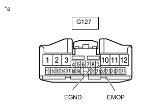
CHECK HARNESS AND CONNECTOR (EGND TERMINAL VOLTAGE)
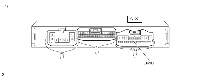
*a Component with harness connected
(Engine Stop and Start ECU)
- -
-
Turn the ignition switch to ON.
-
Measure the voltage according to the value(s) in the table below.
Result Tester Connection Condition Result Proceed to G127-8 (EGND) - Body ground Ignition switch ON 10 to 14 V A Below 1 V B
B
USE SIMULATION METHOD TO CHECK Click here
A
-
-
CHECK HARNESS AND CONNECTOR (EGND TERMINAL VOLTAGE)
*a Component with harness connected
(Engine Stop and Start ECU)
- -
-
Disconnect the C42 transmission wire connector.
-
Turn the ignition switch to ON.
-
Measure the voltage according to the value(s) in the table below.
Result Tester Connection Condition Result Proceed to G127-8 (EGND) - Body ground Ignition switch ON 10 to 14 V A Below 1 V B
B
CHECK HARNESS AND CONNECTOR (EMP+ TERMINAL VOLTAGE) Click here
A
-
-
CHECK HARNESS AND CONNECTOR (EGND TERMINAL VOLTAGE)
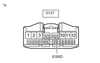
*a Front view of wire harness connector
(to Engine Stop and Start ECU)
-
Disconnect the engine stop and start ECU connector.
-
Turn the ignition switch to ON.
-
Measure the voltage according to the value(s) in the table below.
Result Tester Connection Condition Result Proceed to G127-8 (EGND) - Body ground Ignition switch ON 10 to 14 V A Below 1 V B
A
REPAIR OR REPLACE HARNESS OR CONNECTOR (ENGINE STOP AND START ECU (EGND) - TRANSMISSION WIRE (EMP-))
B
REPLACE ENGINE STOP AND START ECU Click here
-
-
CHECK HARNESS AND CONNECTOR (EMP+ TERMINAL VOLTAGE)
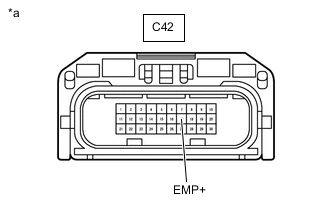
*a Front view of wire harness connector
(to Transmission Wire)
-
Disconnect the C42 transmission wire connector.
-
Turn the ignition switch to ON.
-
Measure the voltage according to the value(s) in the table below.
Result Tester Connection Condition Result Proceed to C42-17 (EMP+) - Body ground Ignition switch ON 10 to 14 V A Below 1 V B
B
INSPECT ELECTROMAGNETIC OIL PUMP Click here
A
-
-
CHECK HARNESS AND CONNECTOR (EMP+ TERMINAL VOLTAGE)
*a Front view of wire harness connector
(to Transmission Wire)
-
Disconnect the G127 engine stop and start ECU connector.
-
Disconnect the transmission wire connector.
-
Turn the ignition switch to ON.
-
Measure the voltage according to the value(s) in the table below.
Result Tester Connection Condition Result Proceed to C42-17 (EMP+) - Body ground Ignition switch ON 10 to 14 V A Below 1 V B
A
REPAIR OR REPLACE HARNESS OR CONNECTOR (ENGINE STOP AND START ECU (EMOP) - TRANSMISSION WIRE (EMP+))
B
REPLACE ENGINE STOP AND START ECU Click here
-
-
INSPECT ELECTROMAGNETIC OIL PUMP
-
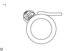
*1 Electromagnetic Oil Pump Remove the electromagnetic oil pump.
-
Measure the resistance according to the value(s) in the table below.
Standard Resistance Tester Connection Condition Specified Condition 1 - 2 20°C (68°F) 5.0 to 5.6 Ω Result Proceed to OK NG
OK
REPLACE TRANSMISSION WIRE Click here
NG
REPLACE ELECTROMAGNETIC OIL PUMP Click here
-
-
CHECK ENGINE STOP AND START ECU (EGND TERMINAL WAVEFORM)
-
Connect an oscilloscope to terminals G127-8 (EGND) and G125-8 (GND1).
-
Enter the following menus: Powertrain / Stop and Start / Active Test / Electromagnetic Oil Pump.
-
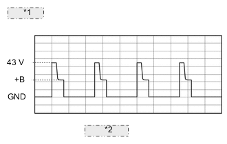
*1 10 V/DIV. *2 20 ms./DIV. Check the waveform while performing the Active Test.
Item Condition Tester Connection G127-8 (EGND) - G125-8 (GND1) Tool Setting 10 V/DIV., 20 ms./DIV. Condition
-
Ignition switch ON (engine is stopped)
-
Active Test "Electromagnetic Oil Pump" being performed
Standard The waveform is similar to that shown in the illustration. Result Result Proceed to Constant value below 1 V A Constant value between 10 to 14 V B Waveform output as in illustration C -
B
REPLACE ENGINE STOP AND START ECU Click here
C
USE SIMULATION METHOD TO CHECK Click here
A
-
-
CHECK HARNESS AND CONNECTOR (ENGINE STOP AND START ECU - BODY GROUND)
*a Component with harness connected
(Engine Stop and Start ECU)
- -
-
Measure the resistance according to the value(s) in the table below.
Result Tester Connection Condition Result Proceed to G127-8 (EGND) - Body ground Ignition switch off Below 1 Ω A 10 kΩ or higher B
B
CHECK HARNESS AND CONNECTOR (EMP+ TERMINAL VOLTAGE) Click here
A
-
-
CHECK HARNESS AND CONNECTOR (ENGINE STOP AND START ECU - BODY GROUND)
*a Front view of wire harness connector
(to Engine Stop and Start ECU)
-
Disconnect the G127 engine stop and start ECU connector.
-
Measure the resistance according to the value(s) in the table below.
Result Tester Connection Condition Result Proceed to G127-8 (EGND) - Body ground Always 10 kΩ or higher A Below 1 Ω B
A
REPLACE ENGINE STOP AND START ECU Click here
B
-
-
CHECK HARNESS AND CONNECTOR (ENGINE STOP AND START ECU - BODY GROUND)
*a Front view of wire harness connector
(to Engine Stop and Start ECU)
-
Disconnect the C42 transmission wire connector.
-
Disconnect the G127 engine stop and start ECU connector.
-
Measure the resistance according to the value(s) in the table below.
Result Tester Connection Condition Result Proceed to G127-8 (EGND) - Body ground Always 10 kΩ or higher A Below 1 Ω B
B
REPAIR OR REPLACE HARNESS OR CONNECTOR
A
-
-
INSPECT ELECTROMAGNETIC OIL PUMP
-
*1 Electromagnetic Oil Pump Remove the electromagnetic oil pump.
-
Measure the resistance according to the value(s) in the table below.
Standard Resistance Tester Connection Condition Specified Condition 1 - 2 20°C (68°F) 5.0 to 5.6 Ω 1 - Body ground Always 10 kΩ or higher Result Proceed to OK NG
OK
REPLACE TRANSMISSION WIRE Click here
NG
REPLACE ELECTROMAGNETIC OIL PUMP Click here
-
-
CHECK HARNESS AND CONNECTOR (EMP+ TERMINAL VOLTAGE)
*a Front view of wire harness connector
(to Transmission Wire)
-
Disconnect the C42 transmission wire connector.
-
Connect the GTS to the DLC3.
-
Turn the ignition switch to ON.
-
Turn the GTS on.
-
Enter the following menus: Powertrain / Stop and Start / Active Test / Electromagnetic Oil Pump.
Powertrain > Stop and Start > Active TestTester Display Electromagnetic Oil Pump -
Measure the voltage according to the value(s) in the table below.
Result Tester Connection Condition Result Proceed to C42-17 (EMP+) - Body ground
-
Ignition switch ON (engine is stopped)
-
Active Test "Electromagnetic Oil Pump" being performed
10 to 14 V A Below 1 V B -
B
CHECK ENGINE STOP AND START ECU (EMOP TERMINAL VOLTAGE) Click here
A
-
-
INSPECT TRANSMISSION WIRE (ELECTROMAGNETIC OIL PUMP)
-
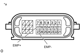
*a Component without harness connected
(Transmission Wire)
Disconnect the C42 transmission wire connector.
-
Measure the resistance according to the value(s) in the table below.
Standard Resistance Tester Connection Condition Specified Condition 17 (EMP+) - 27 (EMP-) 20°C (68°F) 5.0 to 5.6 Ω Result Proceed to OK NG
OK
REPAIR OR REPLACE HARNESS OR CONNECTOR (TRANSMISSION WIRE - ENGINE STOP AND START ECU)
NG
-
-
INSPECT ELECTROMAGNETIC OIL PUMP
-
*1 Electromagnetic Oil Pump Remove the electromagnetic oil pump.
-
Measure the resistance according to the value(s) in the table below.
Standard Resistance Tester Connection Condition Specified Condition 1 - 2 20°C (68°F) 5.0 to 5.6 Ω Result Proceed to OK NG
OK
REPLACE TRANSMISSION WIRE Click here
NG
REPLACE ELECTROMAGNETIC OIL PUMP Click here
-
-
CHECK ENGINE STOP AND START ECU (EMOP TERMINAL VOLTAGE)
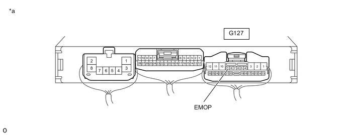
*a Component with harness connected
(Engine Stop and Start ECU)
- -
-
Disconnect the C42 transmission wire connector.
-
Connect the GTS to the DLC3.
-
Turn the ignition switch to ON.
-
Turn the GTS on.
-
Enter the following menus: Powertrain / Stop and Start / Active Test / Electromagnetic Oil Pump.
Powertrain > Stop and Start > Active TestTester Display Electromagnetic Oil Pump -
Measure the voltage according to the value(s) in the table below.
Result Tester Connection Condition Result Proceed to G127-9 (EMOP) - Body ground
-
Ignition switch ON (engine is stopped)
-
Active Test "Electromagnetic Oil Pump" being performed
10 to 14 V A Below 1 V B -
A
REPAIR OR REPLACE HARNESS OR CONNECTOR (TRANSMISSION WIRE - ENGINE STOP AND START ECU)
B
-
-
CHECK CONNECTOR DISCONNECTION
-
Disconnect the C42 transmission wire connector.
-
Disconnect the G127 engine stop and start ECU connector.
-
Measure the resistance according to the value(s) in the table below.
Note
Measure the values on the front side of the connector
Standard Resistance Tester Connection Condition Specified Condition G127-9 (EMOP) - C42-17 (EMP+) Always Below 1 Ω Result Proceed to OK NG
OK
REPLACE ENGINE STOP AND START ECU Click here
NG
REPAIR OR REPLACE HARNESS OR CONNECTOR
-
-
CHECK FREEZE FRAME DATA
Note
The freeze frame data is cleared when DTCs are cleared. Be sure to make a note of necessary data in advance.
-
According to the display on the GTS, select DTC P2796 and check the sets of freeze frame data.
Result Tester Display Result Proceed to Electromagnetic Oil Pump Abnormal When Preliminarily Check ON A Electromagnetic Oil Pump Abnormal When Drive ON B Electromagnetic Oil Pump Abnormal When Preliminarily Check and Electromagnetic Oil Pump Abnormal When Drive OFF C
B
CHECK HARNESS AND CONNECTOR (ENGINE STOP AND START ECU EMOP TERMINAL - EGND TERMINAL) Click here
C
CHECK HARNESS AND CONNECTOR (ENGINE STOP AND START ECU - BODY GROUND) Click here
A
-
-
CHECK HARNESS AND CONNECTOR (ENGINE STOP AND START ECU - BODY GROUND)
*a Component with harness connected
(Engine Stop and Start ECU)
- -
-
Measure the resistance according to the value(s) in the table below.
Standard Resistance Tester Connection Condition Specified Condition G127-9 (EMOP) - Body ground and other terminals Always 10 kΩ or higher Result Proceed to OK NG
OK
GO TO DTC B22C0 Click here
NG
-
-
CHECK HARNESS AND CONNECTOR (ENGINE STOP AND START ECU - BODY GROUND)
*a Component with harness connected
(Engine Stop and Start ECU)
- -
-
Disconnect the C42 transmission wire connector.
-
Measure the resistance according to the value(s) in the table below.
Standard Resistance Tester Connection Condition Specified Condition G127-9 (EMOP) - Body ground and other terminals Always 10 kΩ or higher Result Tester Connection Result Proceed to G127-9 (EMOP) - Body ground and other terminals 10 kΩ or higher A Below 1 Ω B
B
CHECK HARNESS AND CONNECTOR (ENGINE STOP AND START ECU, TRANSMISSION WIRE - BODY GROUND) Click here
A
-
-
INSPECT ELECTROMAGNETIC OIL PUMP
-
*1 Electromagnetic Oil Pump Remove the electromagnetic oil pump.
-
Measure the resistance according to the value(s) in the table below.
Standard Resistance Tester Connection Condition Specified Condition 2 - Body ground Always 10 kΩ or higher Result Proceed to OK NG
OK
REPLACE TRANSMISSION WIRE Click here
NG
REPLACE ELECTROMAGNETIC OIL PUMP Click here
-
-
CHECK HARNESS AND CONNECTOR (ENGINE STOP AND START ECU, TRANSMISSION WIRE - BODY GROUND)
-
Disconnect the C42 transmission wire connector.
-
Disconnect the G127 engine stop and start ECU connector.
-
Measure the resistance according to the value(s) in the table below.
Standard Resistance Tester Connection Condition Specified Condition G127-9 (EMOP) - Body ground and other terminals Always 10 kΩ or higher C42-17 (EMP+) - Body ground and other terminals Always 10 kΩ or higher Result Proceed to OK NG
OK
REPLACE ENGINE STOP AND START ECU Click here
NG
REPAIR OR REPLACE HARNESS OR CONNECTOR (TRANSMISSION WIRE - ENGINE STOP AND START ECU)
-
-
CHECK HARNESS AND CONNECTOR (ENGINE STOP AND START ECU EMOP TERMINAL - EGND TERMINAL)
*a Front view of wire harness connector
(to Engine Stop and Start ECU)
-
Disconnect the G127 engine stop and start ECU connector.
-
Measure the resistance according to the value(s) in the table below.
Standard Resistance Tester Connection Condition Specified Condition G127-9 (EMOP) - G127-8 (EGND) 20°C (68°F) 5.0 to 5.6 Ω Result Proceed to OK NG
OK
REPLACE ENGINE STOP AND START ECU Click here
NG
-
-
CHECK HARNESS AND CONNECTOR (ENGINE STOP AND START ECU EMOP TERMINAL - EGND TERMINAL)
*a Front view of wire harness connector
(to Engine Stop and Start ECU)
-
Disconnect the C42 transmission wire connector.
-
Disconnect G127 the engine stop and start ECU connector.
-
Measure the resistance according to the value(s) in the table below.
Standard Resistance Tester Connection Condition Specified Condition G127-9 (EMOP) - G127-8 (EGND) Always 10 kΩ or higher Result Proceed to OK NG
NG
INSPECT ENGINE STOP AND START SOLENOID FILTER Click here
OK
-
-
INSPECT ELECTROMAGNETIC OIL PUMP
-
*1 Electromagnetic Oil Pump Remove electromagnetic oil pump.
-
Measure the resistance according to the value(s) in the table below.
Standard Resistance Tester Connection Condition Specified Condition 1 - 2 20°C (68°F) 5.0 to 5.6 Ω Result Proceed to OK NG
OK
REPLACE TRANSMISSION WIRE Click here
NG
REPLACE ELECTROMAGNETIC OIL PUMP Click here
-
-
INSPECT ENGINE STOP AND START SOLENOID FILTER
-
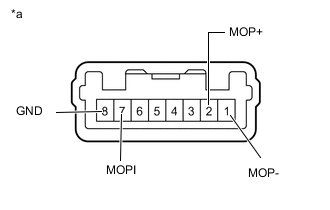
*a Component without harness connected
(Engine Stop and Start Solenoid Filter)
Remove the engine stop and start solenoid filter.
-
Measure the resistance according to the value(s) in the table below.
Standard Resistance Tester Connection Condition Specified Condition 2 (MOP+) - 1 (MOP-) Always 10 kΩ or higher 7 (MOPI) - 8 (GND) Always 10 kΩ or higher Result Proceed to OK NG
OK
REPAIR OR REPLACE HARNESS OR CONNECTOR (TRANSMISSION WIRE - ENGINE STOP AND START ECU)
NG
REPLACE ENGINE STOP AND START SOLENOID FILTER Click here
-
-
CHECK HARNESS AND CONNECTOR (ENGINE STOP AND START ECU - BODY GROUND)
*a Component with harness connected
(Engine Stop and Start ECU)
- -
-
Measure the resistance according to the value(s) in the table below.
Standard Resistance Tester Connection Condition Specified Condition G127-9 (EMOP) - Body ground and other terminals Always 10 kΩ or higher Result Proceed to OK NG
NG
GO TO STEP 21 Click here
OK
-
-
CHECK HARNESS AND CONNECTOR (ENGINE STOP AND START ECU EMOP TERMINAL - EGND TERMINAL)
*a Front view of wire harness connector
(to Engine Stop and Start ECU)
-
Disconnect the G127 engine stop and start ECU connector.
-
Measure the resistance according to the value(s) in the table below.
Standard Resistance Tester Connection Condition Specified Condition G127-9 (EMOP) - G127-8 (EGND) 20°C (68°F) 5.0 to 5.6 Ω Result Proceed to OK NG
NG
GO TO STEP 25 Click here
OK
-
-
CHECK ENGINE STOP AND START ECU
*a Component without harness connected
(Engine Stop and Start ECU)
- -
-
Disconnect the engine stop and start ECU connector.
-
Measure the resistance according to the value(s) in the table below.
Standard Resistance Tester Connection Condition Specified Condition G127-9 (EMOP) - G127-8 (EGND) Always 10 kΩ or higher Result Proceed to OK NG
OK
GO TO DTC B22C0 Click here
NG
REPLACE ENGINE STOP AND START ECU Click here
-