FRONT CAMERA ADJUSTMENT

CAUTION / NOTICE / HINT
Note
When replacing the windshield glass of a vehicle equipped with a forward recognition camera, make sure to use a Toyota genuine part. If a non-Toyota genuine part is used, the forward recognition camera may not be able to be installed due to a missing bracket, or the forward recognition camera system, lane departure alert system, road sign assist system or pre-collision system may not operate properly due to a difference in the transmissivity of the windshield glass or the shape of the black ceramic border.
PROCEDURE
-
PREPARATION FOR FORWARD RECOGNITION CAMERA
-
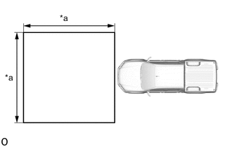
*a 3 m (9.84 ft.) Park the vehicle on a level surface.
Note
-
Make sure that the vehicle is parked on a level surface.
-
Make sure there are no black and white patterned objects in front of the vehicle.
-
Make sure that the area shown in the illustration in front of the vehicle is free of reflective or shiny objects.
-
Perform the following procedures indoors.
-
Perform the following procedures in an area with no wind.
-
Perform the following procedures in a bright area.
-
-
Check that the headlights are turned off.
-
Adjust the tire inflation pressure to the specified pressure.
-
Clean the windshield glass.
-
-
PERFORM FORWARD RECOGNITION CAMERA
-
Create a target sheet.
-
Print the illustration.

-
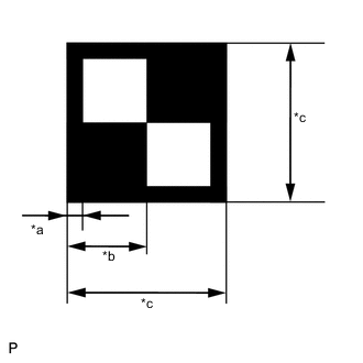
*a 18 mm (0.709 in.) *b 90 mm (3.54 in.) *c 180 mm (7.09 in.) Check that the dimensions are within the values shown in the illustration.
Note
-
Make sure that the black areas of the target sheet are not glossy.
-
Make sure that the borders of the black and white areas on the target sheet are straight, and are not warped or blurry.
Tech Tips
If the dimensions of the created target sheet are not within +/- 5 mm (0.197 in.) of the specified values, adjust the printer settings and reprint the target sheet so that the dimensions are as specified.
-
-
-
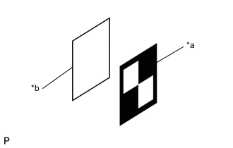
*a Target Sheet *b Cardboard Attach the target sheet.
-
Cut a piece of cardboard to the same size as the target sheet.
-
Place the target sheet on the cardboard with the black area at the top right as shown in the illustration, and securely attach the target sheet using double-sided tape.
Note
Do not attach reflective materials, such as clear adhesive tape, to the target sheet surface as this may affect target recognition.
-
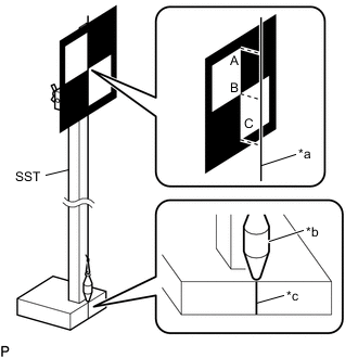
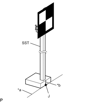
*a String *b Weight *c Mark-off Line Hang a weight with a pointed tip from the top center of the target sheet as shown in the illustration.
- SST
- 09870-60000 ( 09870-60010, 09870-60020 )
-
Using double-sided tape, attach the target sheet to the reflector so that the weight is aligned with the mark-off line of SST.
Tech Tips
Make sure that the points (A), (B) and (C) of the target sheet are aligned with the string.
-
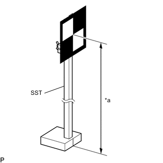
*a 1350 mm (53.15 in.) Move the reflector up or down so that the center of the target sheet is at the height shown in the illustration, and secure the reflector in place.
Tech Tips
If the center of the target sheet is not within +/- 6 mm (0.236 in.) of the height specified, adjust the position of the reflector so that the height is as specified.
-
-
Determine the target placement position.
Note
-
Make sure the background behind the target has no patterns.
-
Make sure that there are no reflective or shiny objects around the target.
-
Make sure that the shadow of the target is not cast onto a wall as this may cause a target recognition error.
-
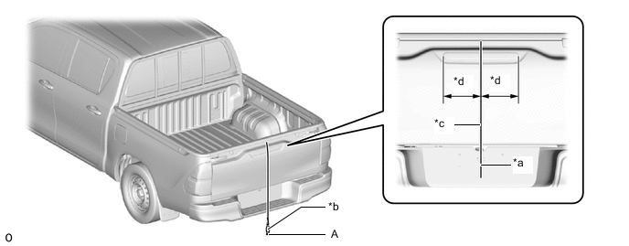
for A Deck:
Hang a weight with a pointed tip from the center of the tail gate handle, and mark the rear center point of the vehicle (point A) on the ground.
*a String *b Weight *c Center *d Bilateral Symmetry Tech Tips
Lightly flick the string with your fingers several times to confirm that the string is perpendicular to the ground.
-
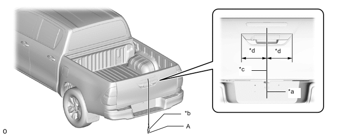
for J Deck:
Hang a weight with a pointed tip from the center of the center stop light assembly, and mark the rear center point of the vehicle (point A) on the ground.
*a String *b Weight *c Center *d Bilateral Symmetry Tech Tips
Lightly flick the string with your fingers several times to confirm that the string is perpendicular to the ground.
-
Hang a weight with a pointed tip from the center of the front emblem, and mark the front center point of the vehicle (point B) on the ground.
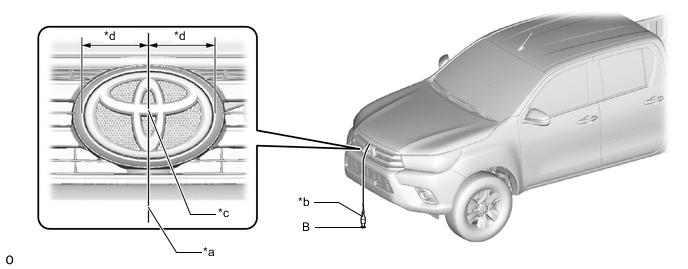
*a String *b Weight *c Center *d Bilateral Symmetry Tech Tips
Lightly flick the string with your fingers several times to confirm that the string is perpendicular to the ground.
-
Using tape and a string, create a line that connects point B to point A and extends at least 2300 mm (7.54 ft.) beyond the front center point of the vehicle.
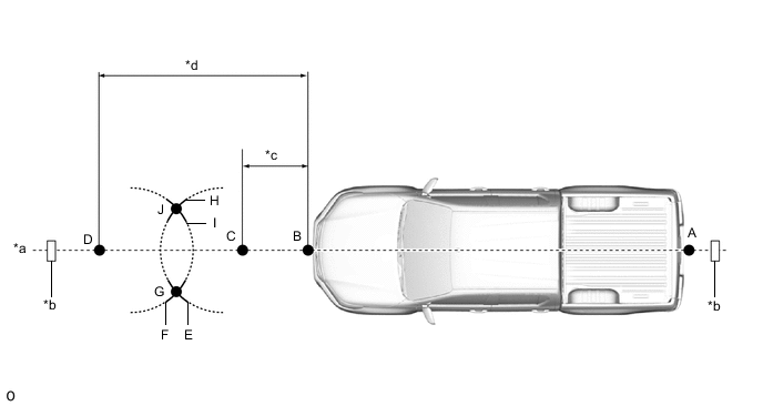
*a Tape *b String *c 392 mm (15.4 in.) *d 2062 mm (6.76 ft.) Tech Tips
-
Make sure the string is taut when securing it with tape.
-
Lightly flick the string with your fingers several times to confirm that the string is aligned with point B.
-
-
Mark point C at a position 392 mm (15.4 in.) in front of point B.
-
Mark point D at a position 2062 mm (6.76 ft.) in front of point B.
-
Using a string, mark line E at a position 1000 mm (3.28 ft.) from point C.
-
Using a string, mark line H at a position 1000 mm (3.28 ft.) from point C.
-
Using a string, mark line F at a position 1000 mm (3.28 ft.) from point D.
-
Using a string, mark line I at a position 1000 mm (3.28 ft.) from point D.
-
Mark point G (placement point 2) at the point where line E and line F intersect.
-
Mark point J (placement point 3) at the point where line H and line I intersect.
-
Using tape and a string, create a line that connects point G and point J (target position line).
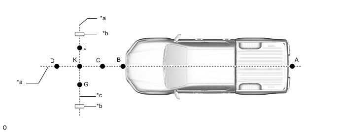
*a String *b Tape *c Target Position Line - - Tech Tips
-
Make sure the string is taut when securing it with tape.
-
Lightly flick the string with your fingers several times to confirm that the string is aligned with points G and J.
-
-
Mark point K (placement position 1) at the point the string connecting points C and D and the string connecting points G and J intersect.
-
Confirm that the distance between points K and G (placement positions 1 and 2), and K and J (placement positions 1 and 3) is 550 mm (21.65 in.).
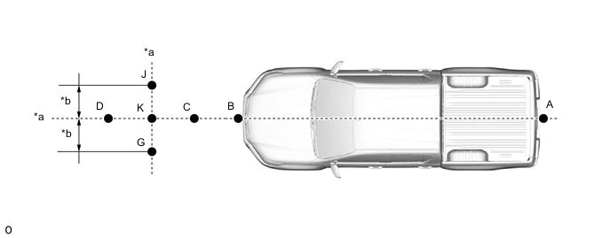
*a String *b 550 mm (21.65 in.) Note
If the distance between either pair of points is not within +/- 3 mm (0.118 in.) mm of the specified value, start over from the marking of point A.
-
-
Perform Recognition Camera/Target Position Memory.
CAUTION:
Do not look into the forward recognition camera from a close distance.
Note
-
Close all of the doors.
-
Make sure that no one is inside the vehicle.
-
Do not lean on the vehicle.
-
Make sure that the headlights are turned off.
-
Connect the GTS to the DLC3.
-
Turn the ignition switch to ON.
-
Turn the GTS on.
-
Enter the following menus:
Chassis > Front Recognition Camera > UtilityTester Display Recognition Camera/Target Position Memory -
According to the display on the GTS, press "Next". *1
-
Confirm the conditions displayed on the screen, and then press "Next".
-
Input "1628 mm (64.09 in.)" for the height of the recognition camera.
-
for LHD, w/o Camera Heater:
Input "101 mm (3.98 in.)" for the lateral position of the recognition camera, then press "Next".
-
for LHD, w/ Camera Heater:
Input "86 mm (3.39 in.)" for the lateral position of the recognition camera, then press "Next".
-
for RHD:
Input "-74 mm (2.91 in.)" for the lateral position of the recognition camera, then press "Next".
-
Input "0 deg" for the yaw angle of the recognition camera.
-
w/o Camera Heater:
Input "-2.31 deg" for the pitch angle of the recognition camera, and then press "Next".
-
w/ Camera Heater:
Input "-5.31 deg" for the pitch angle of the recognition camera, and then press "Next".
-
Input "1350 mm (53.15 in.)" for the height of the target.
-
Input "3000 mm (118.11 in.)" for the distance between the recognition camera and target, and then press "Next".
-
Input "550 mm (21.65 in.)" for the distance between the targets.
-
Input "180 mm (7.09 in.)" for the target size, and then press "Next".
-
Input "1855 mm (73.03 in.)" for the width of the vehicle.
-
Input "856 mm (33.70 in.)" for the distance between the recognition camera and front tires, and then press "Next".
-
Input "0 deg" for the pitch offset angle.
-
Input "1773 mm (69.80 in.)" for the distance between the recognition camera and the radar, and then press "Next".
-
If "Recognition Camera/Target Position Memory has failed." is displayed on the GTS screen, confirm the conditions displayed on the screen, then press "Yes" and repeat the procedure from *1.
-
Press "Exit" to exit the Camera/Target Position Memory utility.
-
-
Perform Recognition Camera Axis Adjust (target positioning).
Note
-
If "Recognition Camera Axis Adjust has failed." is displayed on the screen, confirm the following conditions, turn the ignition switch off and then to ON, and repeat the procedure from *1.
-
Make sure that the height of the target is correct.
-
Make sure that the target placement positions are correct.
-
Make sure that the orientation of the target sheet is correct (black area positioned at the top right).
-
Make sure that the surrounding area is sufficiently bright.
-
Make sure that there are no reflective or shiny objects around the target.
-
Make sure that there are no black and white patterned objects around the target or on a wall near the target.
-
Make sure that the shadow of the target is not cast onto a wall.
-
Make sure that the windshield glass is clean.
-

*a Target Position Line *b Mark-off Line Position SST so that it is aligned with the target position line and the mark-off line is aligned with point K (placement position 1) as shown in the illustration.
- SST
- 09870-60000 ( 09870-60010, 09870-60020 )
-
Enter the following menus:
Chassis > Front Recognition Camera > UtilityTester Display Recognition Camera Axis Adjust -
According to the display on the GTS, press "Next". *1
-
Check that the values stored in the ECU are correct, and then press "Next".
-
Confirm the conditions displayed on the screen, and then press "Next".
-
Select "Sequential recognition", and then press "Next".
-
Check that target is placed at point K (placement position 1), and then press "Next".
-

*a Target Position Line *b Mark-off Line Position SST so that it is aligned with the target position line and the mark-off line is aligned with point G (placement position 2) as shown in the illustration.
- SST
- 09870-60000 ( 09870-60010, 09870-60020 )
Note
Position SST and press "Next" within 3 minutes of the screen changing to the Recognition Camera Axis Adjust screen for point G (placement position 2).
-
*a Target Position Line *b Mark-off Line Position SST so that it is aligned with the target position line and the mark-off line is aligned with point J (placement position 3) as shown in the illustration.
- SST
- 09870-60000 ( 09870-60010, 09870-60020 )
Note
Position SST and press "Next" within 3 minutes of the screen changing to the Recognition Camera Axis Adjust screen for point J (placement position 3).
-
If "Failed to read axis adjustment data" is displayed, perform Recognition Camera/Target Position Memory, and repeat the procedure from *1.
-
Press the "Exit" button to finish camera axis learning mode.
-
Turn the ignition switch off.
-
Disconnect the GTS from the DLC3.
-
-