CRUISE CONTROL SYSTEM, Diagnostic DTC:P0571
| DTC Code | DTC Name |
|---|---|
| P0571 | Brake Switch "A" Circuit |
DESCRIPTION
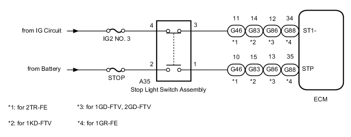
When the brake pedal is depressed, the stop light switch assembly sends a signal to the ECM. Upon receiving the signal, the ECM cancels the cruise control system.
| DTC No. | Detection Item | DTC Detection Condition | Trouble Area |
|---|---|---|---|
| P0571 | Brake Switch "A" Circuit | When voltage of STP terminal and that of ST1- terminal of ECM are less than 1 V for 0.5 seconds or more |
|
WIRING DIAGRAM
CAUTION / NOTICE / HINT
Note
Inspect the fuses for circuits related to this system before performing the following procedure.
PROCEDURE
-
CHECK HARNESS AND CONNECTOR (STOP LIGHT SWITCH ASSEMBLY - BATTERY)
-
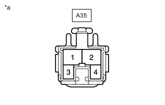
*a Front view of wire harness connector
(to Stop Light Switch Assembly)
Disconnect the stop light switch assembly connector.
-
Measure the voltage according to the value(s) in the table below.
Standard Voltage Tester Connection Condition Specified Condition A35-2 - Body ground Always 11 to 14 V A35-4 - Body ground Ignition switch ON 11 to 14 V A35-4 - Body ground Ignition switch off Below 1 V Result Proceed to OK NG
NG 
REPAIR OR REPLACE HARNESS OR CONNECTOR
OK 
-
-
INSPECT STOP LIGHT SWITCH ASSEMBLY
-
Remove the stop light switch assembly.
-
Inspect the stop light switch assembly.
Result Proceed to OK NG
NG
REPLACE STOP LIGHT SWITCH ASSEMBLY Click here
OK
-
-
CHECK HARNESS AND CONNECTOR (ECM - STOP LIGHT SWITCH ASSEMBLY)
-
for 2TR-FE
-
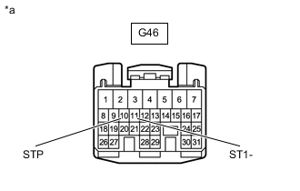
*a Front view of wire harness connector
(to ECM)
Disconnect the ECM connector.
-
Measure the voltage according to the value(s) in the table below.
Standard Voltage Tester Connection Condition Specified Condition G46-11 (ST1-) - Body ground Ignition switch ON, brake pedal depressed Below 1.5 V Ignition switch ON, brake pedal released 7.5 to 14 V G46-10 (STP) - Body ground Brake pedal depressed 7.5 to 14 V Brake pedal released Below 1.5 V
-
-
for 1KD-FTV
-
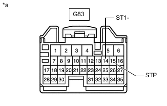
*a Front view of wire harness connector
(to ECM)
Disconnect the ECM connector.
-
Measure the voltage according to the value(s) in the table below.
Standard Voltage Tester Connection Condition Specified Condition G83-14 (ST1-) - Body ground Ignition switch ON, brake pedal depressed 0 to 1.5 V Ignition switch ON, brake pedal released 7.5 to 14 V G83-15 (STP) - Body ground Brake pedal depressed 7.5 to 14 V Brake pedal released 0 to 1.5 V
-
-
for 1GD-FTV, 2GD-FTV
-
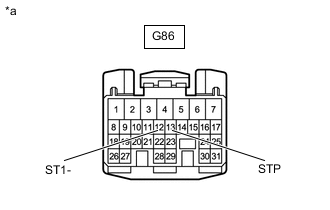
*a Front view of wire harness connector
(to ECM)
Disconnect the ECM connector.
-
Measure the voltage according to the value(s) in the table below.
Standard Voltage Tester Connection Condition Specified Condition G86-12 (ST1-) - Body ground Ignition switch ON, brake pedal depressed 0 to 1.5 V Ignition switch ON, brake pedal released 7.5 to 14 V G86-13 (STP) - Body ground Brake pedal depressed 7.5 to 14 V Brake pedal released 0 to 1.5 V
-
-
for 1GR-FE
-
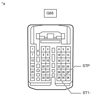
*a Front view of wire harness connector
(to ECM)
Disconnect the ECM connector.
-
Measure the voltage according to the value(s) in the table below.
Standard Voltage Tester Connection Condition Specified Condition G88-34 (ST1-) - Body ground Ignition switch ON, brake pedal depressed Below 1.5 V Ignition switch ON, brake pedal released 7.5 to 14 V G88-35 (STP) - Body ground Brake pedal depressed 7.5 to 14 V Brake pedal released Below 1.5 V
Result Proceed to OK NG -
OK
REPLACE ECM for 1GR-FE: Click here
REPLACE ECM for 2TR-FE: Click here
REPLACE ECM for 1GD-FTV: Click here
REPLACE ECM for 2GD-FTV: Click here
REPLACE ECM for 1KD-FTV: Click hereNG
REPAIR OR REPLACE HARNESS OR CONNECTOR
-