CRUISE CONTROL SYSTEM TERMINALS OF ECU
-
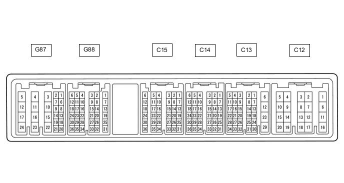
CHECK ECM (for 1GR-FE)
Tech Tips
Each ECM terminal's standard voltage is shown in the table below.
In the table, first follow the information under "Condition". Look under "Terminal No. (Symbol)" for the terminals to be inspected. The standard voltage between the terminals is shown under "Specified Condition".
Use the illustration above as a reference for the ECM terminals.
Terminal No. (Symbol) Wiring Color Terminal Description Condition Specified Condition C13-12 (E1) - Body ground BR - Body ground Ground Always Below 1 Ω C15-22 (D) - C13-12 (E1) GR - BR D shift position switch signal Ignition switch ON and shift lever in D, S, "+" or "-" 11 to 14 V Ignition switch ON and shift lever not in D, S, "+" or "-" Below 1 V G87-24 (BATT) - C13-12 (E1) Y - BR Battery (for measuring battery voltage and for ECM memory) Always 11 to 14 V G88-9 (SFTD) - C13-12 (E1) G - BR Down-shift position switch signal Ignition switch ON and shift lever in S 11 to 14 V Ignition switch ON and shift lever in "-" (down-shift) Below 1 V G88-15 (SFTU) - C13-12 (E1) W - BR Up-shift position switch signal Ignition switch ON and shift lever in S 11 to 14 V Ignition switch ON and shift lever in "+" (up-shift) Below 1 V G88-22 (S) - C13-12 (E1) L - BR S shift position switch signal Ignition switch ON and shift lever in S, "+" or "-" 11 to 14 V Ignition switch ON and shift lever not in S, "+" or "-" Below 1 V G88-1 (CCS) - C13-12 (E1) G - BR Cruise control switch circuit Cruise control main switch off 1 MΩ or higher Cruise control main switch on Below 2.5 Ω +RES switch on 235 to 245 Ω -SET switch on 617 to 643 Ω CANCEL switch on 1509 to 1571 Ω G88-34 (ST1-) - C13-12 (E1) GR - BR Stop light switch assembly signal (opposite of voltage at STP terminal) Ignition switch ON,
brake pedal depressed
Below 1.5 V Ignition switch ON,
brake pedal released
7.5 to 14 V G88-35 (STP) - C13-12 (E1) L - BR Stop light switch assembly signal Brake pedal depressed 7.5 to 14 V Brake pedal released Below 1.5 V -
CHECK ECM (for 2TR-FE)
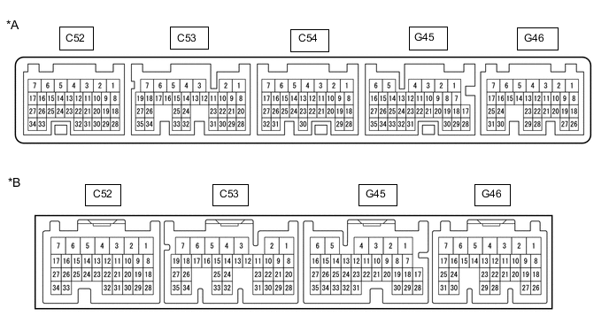
*A for Automatic Transmission *B for Manual Transmission Tech Tips
Each ECM terminal's standard voltage is shown in the table below.
In the table, first follow the information under "Condition". Look under "Terminal No. (Symbol)" for the terminals to be inspected. The standard voltage between the terminals is shown under "Specified Condition".
Use the illustration above as a reference for the ECM terminals.
Terminal No. (Symbol) Wiring Color Terminal Description Condition Specified Condition C52-3 (E1) - Body ground W-B - Body ground Ground Always Below 1 Ω C54-17 (SFTU) - C52-3 (E1)*2 W - W-B Up-shift position switch signal Ignition switch ON and shift lever in S 11 to 14 V Ignition switch ON and shift lever in "+" position (up-shift) Below 1 V C54-27 (SFTD) - C52-3 (E1)*2 G - W-B Down-shift position switch signal Ignition switch ON and shift lever in S 11 to 14 V Ignition switch ON and shift lever in "-" (down-shift) Below 1 V C54-30 (S) - C52-3 (E1)*2 L - W-B S shift position switch signal Ignition switch ON and shift lever in S, "+" or "-" 11 to 14 V Ignition switch ON and shift lever not in S, "+" or "-" Below 1 V G45-18 (D) - C52-3 (E1)*1 P - W-B Clutch switch signal Ignition switch ON, clutch pedal depressed Below 1 V Ignition switch ON, clutch pedal released 11 to 14 V G45-18 (D) - C52-3 (E1)*2 P - W-B D shift position signal Ignition switch ON and shift lever in D, S, "+" or "-" 11 to 14 V Ignition switch ON and shift lever not in D, S, "+" or "-" Below 1 V G45-22 (CCS) - G45-21 (ECCS) G - BR Cruise control switch circuit Cruise control main switch off 1 MΩ or higher Cruise control main switch on Below 2.5 Ω +RES switch on 235 to 245 Ω -SET switch on 617 to 643 Ω CANCEL switch on 1509 to 1571 Ω G46-3 (BATT) - C52-3 (E1) Y - W-B Battery (for measuring battery voltage and for ECM memory) Always 11 to 14 V G46-10 (STP) - C52-3 (E1) L - W-B Stop light switch assembly signal Brake pedal depressed 7.5 to 14 V Brake pedal released Below 1.5 V G46-11 (ST1-) - C52-3 (E1) GR - W-B Stop light switch assembly signal
(opposite to voltage at STP terminal)
Ignition switch ON,
brake pedal depressed
Below 1.5 V Ignition switch ON,
brake pedal released
7.5 to 14 V
-
*1: for Manual Transmission
-
*2: for Automatic Transmission
-
-
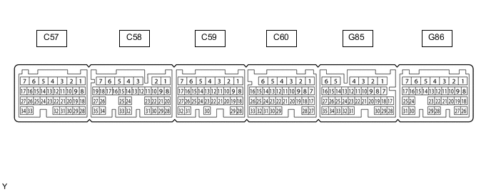
CHECK ECM (for 1GD-FTV, 2GD-FTV)
Tech Tips
Each ECM terminal's standard voltage is shown in the table below.
In the table, first follow the information under "Condition". Look under "Terminal No. (Symbol)" for the terminals to be inspected. The standard voltage between the terminals is shown under "Specified Condition".
Use the illustration above as a reference for the ECM terminals.
Terminal No. (Symbol) Wiring Color Terminal Description Condition Specified Condition C57-14 (D) - C60-1 (E1)*1 GR - W-B Clutch switch signal Ignition switch ON, clutch pedal depressed Below 1 V Ignition switch ON, clutch pedal released 11 to 14 V C57-14 (D) - C60-1 (E1)*2 GR - W-B D shift position signal Ignition switch ON and shift lever in D, S, "+" or "-" 11 to 14 V Ignition switch ON and shift lever not in D, S, "+" or "-" Below 1 V C60-1 (E1) - Body ground W-B - Body ground Ground Always Below 1 Ω G85-13 (S) - C60-1 (E1)*2 L - W-B S shift position switch signal Ignition switch ON and shift lever in S, "+" or "-" 11 to 14 V Ignition switch ON and shift lever not in S, "+" or "-" Below 1 V G85-20 (SFTD) - C60-1 (E1)*2 G - W-B Down-shift switch signal Ignition switch ON and shift lever in S 11 to 14 V Ignition switch ON and shift lever in "-" (down-shift) Below 1 V G85-21 (SFTU) - C60-1 (E1)*2 W - W-B Up-shift switch signal Ignition switch ON and shift lever in S 11 to 14 V Ignition switch ON and shift lever in "+" (up-shift) Below 1 V G86-1 (BATT) - C60-1 (E1) Y - W-B Battery (for measuring battery voltage and for ECM memory) Always 11 to 14 V G86-12 (ST1-) - C60-1 (E1) GR - W-B Stop light switch assembly signal
(opposite to voltage at STP terminal)
Ignition switch ON,
brake pedal depressed
0 to 1.5 V Ignition switch ON,
brake pedal released
7.5 to 14 V G86-13 (STP) - C60-1 (E1) L - W-B Stop light switch assembly signal Brake pedal depressed 7.5 to 14 V Brake pedal released 0 to 1.5 V G86-26 (CCS) - C60-1 (E1) G - W-B Cruise control switch circuit Cruise control main switch off 1 MΩ or higher Cruise control main switch on Below 2.5 Ω +RES switch on 235 to 245 Ω -SET switch on 617 to 643 Ω CANCEL switch on 1509 to 1571 Ω
-
*1: for Manual Transmission
-
*2: for Automatic Transmission
-
-
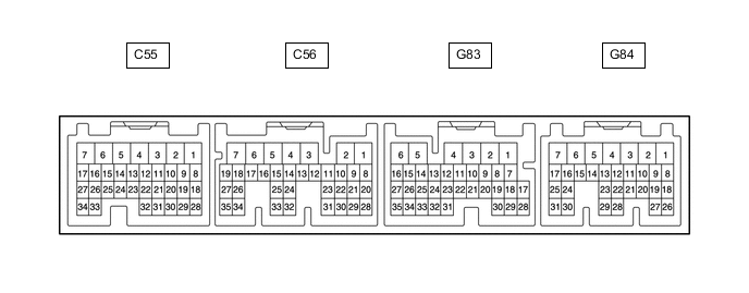
CHECK ECM (for 1KD-FTV)
Tech Tips
Each ECM terminal's standard voltage is shown in the table below.
In the table, first follow the information under "Condition". Look under "Terminal No. (Symbol)" for the terminals to be inspected. The standard voltage between the terminals is shown under "Specified Condition".
Use the illustration above as a reference for the ECM terminals.
Terminal No. (Symbol) Wiring Color Terminal Description Condition Specified Condition C56-7 (E1) - Body ground W-B - Body ground Ground Always Below 1 Ω G83-2 (BATT) - C56-7 (E1) Y - W-B Battery (for measuring the battery voltage and for the ECM memory) Always 11 to 14 V G83-14 (ST1-) - C56-7 (E1) GR - W-B Stop light switch assembly signal
(opposite to voltage at STP terminal)
Ignition switch ON,
brake pedal depressed
0 to 1.5 V Ignition switch ON,
brake pedal released
7.5 to 14 V G83-15 (STP) - C56-7 (E1) L - W-B Stop light switch assembly signal Brake pedal depressed 7.5 to 14 V Brake pedal released 0 to 1.5 V G84-21 (CCS) - C56-7 (E1) G - W-B Cruise control switch circuit Cruise control main switch off 1 MΩ or higher Cruise control main switch on Below 2.5 Ω +RES switch on 235 to 245 Ω -SET switch on 617 to 643 Ω CANCEL switch on 1509 to 1571 Ω -
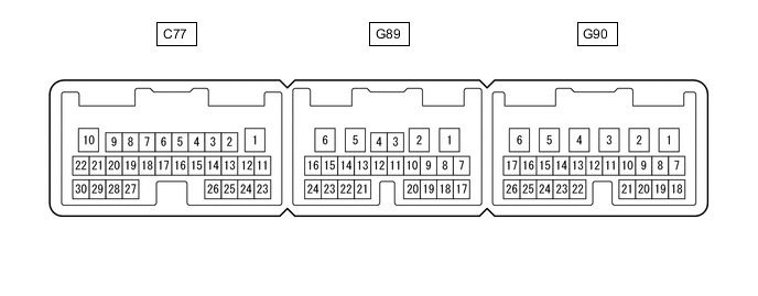
CHECK TCM (for 1KD-FTV)
Tech Tips
Each TCM terminal's standard voltage is shown in the table below.
In the table, first follow the information under "Condition". Look under "Terminal No. (Symbol)" for the terminals to be inspected. The standard voltage between the terminals is shown under "Specified Condition".
Use the illustration above as a reference for the TCM terminals.
Terminal No. (Symbol) Wiring Color Terminal Description Condition Specified Condition G89-8 (D) - C77-1 (E1) P - W-B D shift position switch signal Ignition switch ON and shift lever in D, S, "+" or "-" 11 to 14 V Ignition switch ON and shift lever not in S, "+" or "-" Below 1 V C77-1 (E1) - Body ground W-B - Body ground Ground Always Below 1 Ω G90-15 (S) - C77-1 (E1) L - W-B S shift position switch signal Ignition switch ON and shift lever in S, "+" or "-" 11 to 14 V Ignition switch ON and shift lever not in S, "+" or "-" Below 1 V G90-22 (SFTU) - C77-1 (E1) W - W-B Up-shift position switch signal Ignition switch ON and shift lever in S 11 to 14 V Ignition switch ON and shift lever in "+" position (up-shift) Below 1 V G90-23 (SFTD) - C77-1 (E1) G - W-B Down-shift position switch signal Ignition switch ON and shift lever in S 11 to 14 V Ignition switch ON and shift lever in "-" (down-shift) Below 1 V