PROCEDURE
- Click here
INSPECT STARTER ASSEMBLY
CAUTION:As a large electric current passes through the cable during this inspection, a thick cable must be used. Otherwise, the cable may become hot and cause injury.
Note:The following tests must each be performed within 3 to 5 seconds to prevent the coil from burning out.
-
Mount the starter in a vise between aluminum plates.
-
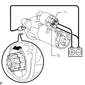
*1 Terminal 50 *2 Terminal C 
Moves outward Perform a pull-in test.
-
Remove the nut, and then disconnect the lead wire from terminal C.
-
Connect the battery to the magnet starter switch as shown in the illustration. Then check that the clutch pinion gear moves outward.
If the clutch pinion gear does not move, replace the magnet starter switch assembly.
-
-
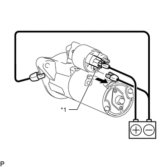
*1 Terminal C Disconnect Perform a holding test.
-
Disconnect the negative (-) terminal lead from terminal C with the condition specified in the pull-in test above being maintained. Check that the pinion gear remains out.
If the clutch pinion gear returns inward, replace the magnet starter switch assembly.
-
-
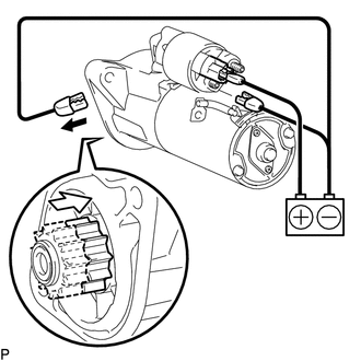
Disconnect 
Returns inward Inspect the clutch pinion gear return.
-
Disconnect the negative (-) lead from the starter body. Check that the clutch pinion gear returns inward.
If the clutch pinion gear does not return inward, replace the magnet starter switch assembly.
-
-
Perform an operation test without load.
-
Connect the lead wire to terminal C.
8.0 N*m 82 kgf*cm 71 in.*lbf -
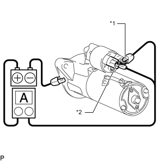
*1 Terminal 30 *2 Terminal 50 Connect the battery and an ammeter to the starter as shown in the illustration.
-
Check that the starter rotates smoothly and steadily while the pinion gear is moving outward. Then measure the current.
Standard current 123 A or less at 10.9 V If the result is not as specified, replace the starter assembly.
-
-