STARTER(w/ Stop And Start System) INSPECTION
PROCEDURE
-
INSPECT STARTER ASSEMBLY
CAUTION:
As a large electric current passes through the cable during this inspection, a thick cable must be used. Otherwise, the cable may become hot and cause injury.
Note
These tests must be performed within 3 to 5 seconds to avoid burning out the coil.
Tech Tips
When replacing the starter assembly, it is necessary to replace the ST1 relay and ST2 relay.
-
Mount the starter assembly in a vise between aluminum plates.
-
Perform a no-load performance test.
-
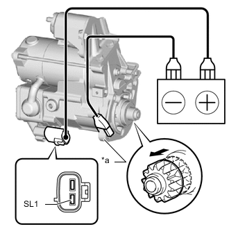
*a Starter Body 
Moves Outward Connect the positive (+) lead to terminal SL1.
-
Connect the negative (-) lead to the starter body and check that the clutch pinion gear moves outward.
Note
Be careful when connecting the leads, as the starter assembly may be damaged if the leads are connecting to the wrong locations.
If the clutch pinion gear does not extend, replace the starter assembly, ST1 relay and ST2 relay.
-
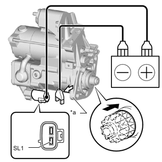
*a Starter Body Return Inward 
Disconnect With the clutch pinion gear in the outward position, disconnect the negative (-) lead and check that the clutch pinion gear returns inward.
If the clutch pinion gear does not return inward, replace the starter assembly, ST1 relay and ST2 relay.
-
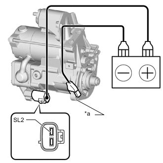
*a Starter Body Connect the positive (+) lead to terminal SL2 of the connector and the negative (-) lead to the starter body. Check that a clicking sound is heard from the starter motor.
Note
Be careful when connecting the leads, as the starter assembly may be damaged if the leads are connecting to the wrong locations.
If the result is not as specified, replace the starter assembly, ST1 relay and ST2 relay.
-
Connect the battery and an ammeter (AC/DC 400A probe) to the starter assembly as shown in the illustration.

*a Terminal 30 *b Starter Body *c AC/DC 400A Probe - - Note
Be careful when connecting the leads, as the starter assembly may be damaged if the leads are connecting to the wrong locations.
-
Connect the negative (-) battery cable and measure the current after the ammeter (AC/DC 400A probe) reading has stabilized.
Current criteria 160 A or less at 11 V Tech Tips
When replacing the starter assembly, it is necessary to replace the ST1 relay and ST2 relay.
If the result is not as specified, replace the starter assembly, ST1 relay and ST2 relay.
-
-
Check the starter clutch.
-
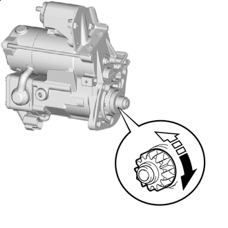
Free Lock Rotate the clutch pinion gear clockwise and check that it turns freely. Try to rotate the clutch pinion gear counterclockwise and check that it locks.
Tech Tips
When replacing the starter assembly, it is necessary to replace the ST1 relay and ST2 relay.
If the result is not as specified, replace the starter assembly, ST1 relay and ST2 relay.
-
-