STARTER(for 2.2 kW Type) INSPECTION
PROCEDURE
-
INSPECT STARTER ASSEMBLY
CAUTION:
As a large electric current passes through the cable during this inspection, a thick cable must be used. Otherwise, the cable may become hot and cause injury.
Note
These tests must be performed within 3 to 5 seconds to prevent the coil from burning out.
-
Mount the starter assembly in a vise between aluminum plates.
-
Perform pull-in test.
-
Remove the nut and disconnect the lead wire from terminal C.
-
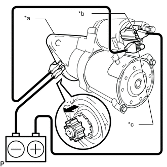
*a Starter Body *b Terminal 50 *c Terminal C Connect the battery to the magnet starter switch assembly as shown in the illustration. Then check that the clutch pinion gear moves outward.
If the clutch pinion gear does not move, replace the magnet starter switch assembly.
-
-
Perform holding test.
-
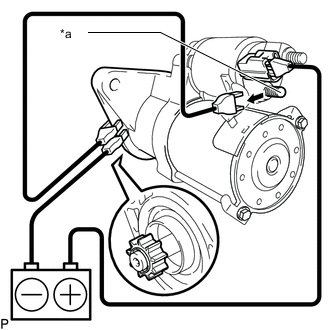
*a Terminal C 
Disconnect When the battery is connected as above with the clutch pinion gear out, disconnect the negative (-) lead from terminal C. Check that the pinion gear remains out.
If the clutch pinion gear returns inward, replace the magnet starter switch assembly.
-
-
Inspect clutch pinion gear return.
-
Disconnect 
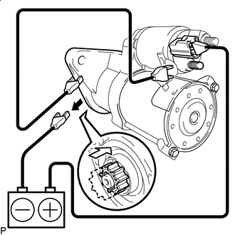
Return Inward Disconnect the negative (-) lead from the starter body. Check that the clutch pinion gear returns inward.
If the clutch pinion gear does not return inward, replace the magnet starter switch assembly.
-
-
Perform operation test without load.
-
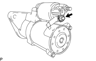
Connect the lead wire to terminal C with the nut.
- Torque:
- 9.8 N*m { 100 kgf*cm, 87 in.*lbf }
-
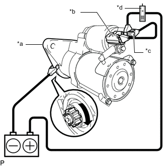
*a Starter Body *b Terminal 50 *c Terminal 30 *d AC/DC 400A Probe Connect the battery and an ammeter (AC/DC 400A probe) to the starter assembly as shown in the illustration.
-
Check that the starter rotates smoothly and steadily while the clutch pinion gear is extended. Then measure the current.
Standard current 120 A or less at 11 V If the result is not as specified, replace the starter assembly.
-
-
-
INSPECT STARTER DRIVE HOUSING
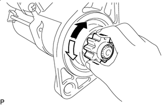
Free Lock
-
Rotate the clutch pinion gear clockwise and check that it turns freely. Try to rotate the clutch pinion gear counterclockwise and check that it locks.
If the result is not as specified, replace the starter drive housing.
-
Turn the clutch pinion gear by hand while applying inward force and check the movement of the bearing.
If resistance is felt or the bearing sticks, replace the starter drive housing.
-