INTAKE SYSTEM ON-VEHICLE INSPECTION

PROCEDURE
-
CHECK INTAKE AIR SYSTEM
-
Check that there is no air suction or leaks at the points shown in the illustration.
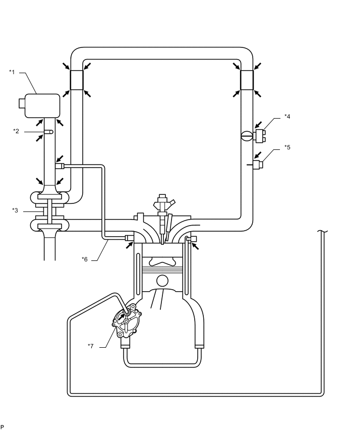
*1 Air Cleaner Assembly *2 Intake Air Temperature Sensor *3 Turbocharger Sub-assembly *4 Diesel Throttle Body *5 Manifold Absolute Pressure Sensor *6 PCV Hose *7 Vacuum Pump - - -
Check for leakage or clogging between the air cleaner housing and turbocharger inlet, and between the turbocharger outlet and cylinder head.
Condition Operation Clogged air cleaner Clean or replace Collapsed or deformed hoses Repair or replace Leakage from connections Check each connection and repair Cracks in components Check and replace
-
-
CHECK EXHAUST SYSTEM
-
Check for leakage or clogging between the cylinder head and turbocharger inlet, and between the turbocharger outlet and exhaust pipe.
Condition Operation Deformed components Repair or replace Foreign matter in passages Remove Leakage from components Repair or replace Cracks in components Check and replace
-
-
CHECK BOOST PRESSURE
-
Warm up the engine.
Tech Tips
Be sure to perform the inspection when the engine coolant temperature is between 75 and 90°C (167 and 194°F).
-
Fully apply the parking brake and chock the 4 wheels.
-
Using a 3-way connector, connect SST (turbocharger pressure gauge) to the hose between the manifold absolute pressure sensor and the gas filter leading to the intake air connector.
- SST
- 09992-00242
-
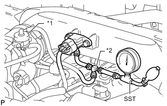
*1 Gas Filter *2 3-Way Connector While depressing the clutch pedal, fully depress the accelerator pedal. Measure the boost pressure at maximum engine speed (approximately 4600 rpm).
Standard pressure (Gauge pressure) 53 to 83 kPa (0.5 to 0.8 kgf/cm2, 7.7 to 12 psi) If the pressure is below the standard, the following problems may be present.
-
The intake system or exhaust system has leakage or blockage.
-
The turbocharger sub-assembly is malfunctioning.
-
The diesel throttle body does not open.
-
The vacuum hose connected to the diesel turbo pressure sensor (manifold absolute pressure sensor) is cracked or disconnected.
-
The mass air flow meter is malfunctioning.
-
A fuel injector is malfunctioning.
If the pressure is higher than the standard, check the turbocharger and/or boost control components (pressure sensor, vacuum hose, etc.).
-
-
Chart showing the suspected trouble areas when the pressure is below the standard.
Tech Tips
-
○: If a problem listed in the leftmost column of the chart exists, or if the part in the leftmost column of the chart has a malfunction, the value of the Data List item in the uppermost row of the chart will meet the conditions shown in the row labeled "Value which represents a malfunction".
-
The values in the chart are applicable when the engine coolant temperature is between 75 and 90°C (167 and 194°F).
-
The values in the chart are valid in an area with an absolute atmospheric pressure higher than 95 kPa. Standard atmospheric pressure is 101 kPa. Atmospheric pressure decreases by 1 kPa for every 100 m increase in altitude, and is also affected by the current weather conditions.
-
When the altitude increases, atmospheric pressure and MAP decrease.
Item MAP
(Absolute pressure inside intake manifold)
Accel Position Actual Throttle Position Fuel Pressure Injection Feedback Val #1 (to #4) Values taken from an actual normal vehicle
*1
- 99% or more None - -3 to +3 mm3/st
Values which represent a malfunction
*1
None Accel Position is not fully depressed position
*2
None Fuel Pressure is below Target Common Rail Pressure by 10 MPa or more (Check while condition steady) Outside of above range Turbocharger ○ - - - - Problem with diesel throttle movement ○
(Intake airflow decreases)
- ○ - - Accelerator pedal cannot be fully depressed or problem with accelerator pedal position sensor exists - ○ - - - Intake air system leakage or blockage ○ - - - - Exhaust gas leakage before turbocharger or blockage ○ - - - - Manifold absolute pressure sensor ○ - - - - Manifold absolute pressure sensor hose is disconnected ○ - - - - Mass air flow meter sub-assembly - - - - - Fuel system (injector, supply pump or common rail) ○ - - ○
(Fuel injector leakage, decrease in pressure discharge valve relief pressure or valve is stuck)
○
*5
Tech Tips
-
*1: These values are measured when the transmission is in 2nd gear, the accelerator pedal is fully depressed, the vehicle is accelerating, and the engine speed is 3000 rpm.
-
*2: The Accel Position is the accelerator opening angle (%) for engine control use. The value indicates around 100% when the accelerator pedal fully depressed. If the value does not indicate around 100% when the accelerator pedal fully depressed, the accelerator pedal position sensor circuit or the pedal itself is malfunctioning. When the MIL is illuminated, even with the accelerator pedal fully depressed and an Accel Position of below 70%, it means the fail-safe is restricting the accelerator.
-
*3: If injection Feedback Val # of a cylinder is not within -3 to +3 mm3/st, the corresponding cylinder may have a malfunction (injector or compression). However, in some cases the cylinder may be malfunctioning even if the value is within -3 to +3 mm3/st because these values are injection volume correction values calculated by the ECM at the engine idling and not correction values for the high engine load condition related to the boost pressure control and engine output performance.
-
-