INTAKE MANIFOLD INSTALLATION

CAUTION / NOTICE / HINT
Note
-
When replacing the parts in the following chart (A), replace the No. 1 injection pipe sub-assembly, No. 2 injection pipe sub-assembly and/or fuel inlet pipe sub-assembly with new ones.
Replaced Parts (A) Pipes Requiring New Replacement
-
Injector assembly (including shuffling the injector assemblies between the cylinders)
-
No. 1 injection pipe sub-assembly
-
No. 2 injection pipe sub-assembly
-
Supply pump assembly
-
Fuel inlet pipe sub-assembly
-
Common rail assembly
-
Cylinder block sub-assembly
-
Cylinder head sub-assembly
-
Cylinder head gasket
-
Timing chain case assembly
-
No. 1 injection pipe sub-assembly
-
No. 2 injection pipe sub-assembly
-
Fuel inlet pipe sub-assembly
-
-
After removing the No. 1 injection pipe sub-assembly, No. 2 injection pipe sub-assembly and/or fuel inlet pipe sub-assembly, clean them with a brush and compressed air.
PROCEDURE
-
INSTALL INTAKE MANIFOLD
-
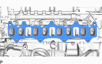
*a Protrusion Install a new gasket to the cylinder head sub-assembly.
Tech Tips
Install the gasket with the protrusion the rear side of the vehicle as shown in the illustration.
-
Temporarily install the intake manifold with the 7 bolts and 2 nuts.
-
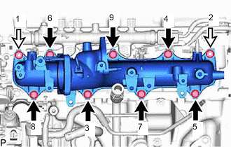

Bolt 
Nut Tighten the 7 bolts and 2 nuts in the order shown in the illustration.
- Torque:
- 23 N*m { 235 kgf*cm, 17 ft.*lbf }
-
Connect the vacuum hose assembly to the vacuum transmitting pipe sub-assembly.
-
Connect the wire harness bracket with the bolt.
- Torque:
- 18.6 N*m { 190 kgf*cm, 14 ft.*lbf }
-
-
INSTALL NO. 2 NOZZLE LEAKAGE PIPE ASSEMBLY
-
Install the No. 2 nozzle leakage pipe assembly with the 2 bolts.
- Torque:
- 10 N*m { 102 kgf*cm, 7 ft.*lbf }
-
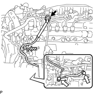
Connect the No. 6 fuel hose to the No. 3 nozzle leakage pipe assembly and slide the clamp to secure the hoses.
-
Install the No. 4 fuel hose and No. 5 fuel hose to the No. 2 nozzle leakage pipe assembly, and slide the 4 clamps to secure the hose.
-
-
INSTALL FUEL INLET PIPE SUB-ASSEMBLY
Note
When replacing the fuel supply pump assembly, it is necessary to replace the fuel inlet pipe sub-assembly, No. 1 injection pipe clamp and No. 2 injection pipe clamp with a new one.
Keep the fuel inlet pipe sub-assembly free of foreign matter.
-
Temporarily install the fuel inlet pipe sub-assembly.
-
Install new No. 1 injection pipe clamp and No. 2 injection pipe clamp with the 2 bolts.
- Torque:
- 10 N*m { 102 kgf*cm, 7 ft.*lbf }
-
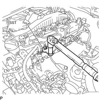
Using SST, tighten the fuel inlet pipe sub-assembly union nut on the common rail side sub-assembly.
- SST
- 09245-11010
- Torque:
- Specified tightening torque
- 40 N*m { 408 kgf*cm, 30 ft.*lbf }
Tech Tips
-
Calculate the torque wrench reading when changing the fulcrum length of the torque wrench.
-
When using a union nut wrench (fulcrum length of 50 mm (1.97 in.)) + torque wrench (fulcrum length of 180 mm (7.09 in.)): 31 N*m (316 kgf*cm, 23 ft.*lbf)
-
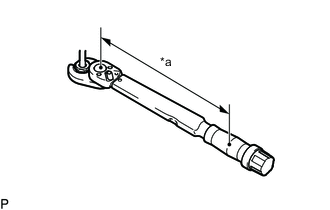
*a Torque Wrench Fulcrum Length Using a 19 mm union nut wrench, tighten the fuel inlet pipe sub-assembly union nut on the fuel supply pump assembly side.
- Torque:
- Specified tightening torque
- 48 N*m { 489 kgf*cm, 35 ft.*lbf }
Tech Tips
-
Calculate the torque wrench reading when changing the fulcrum length of the torque wrench.
-
When using a union nut wrench (fulcrum length of 30 mm (1.18 in.)) + torque wrench (fulcrum length of 180 mm (7.09 in.)): 41 N*m (418 kgf*cm, 30 ft.*lbf)
-
-
INSTALL MANIFOLD STAY
-
Install the manifold stay with the 2 bolts.
- Torque:
- 21 N*m { 214 kgf*cm, 15 ft.*lbf }
-
Install the wiring harness clamp bracket with the bolt.
- Torque:
- 12.6 N*m { 128 kgf*cm, 9 ft.*lbf }
-
-
INSTALL NO. 3 FUEL PIPE (w/ DPF or Pressurized Fuel Filter)
-
Temporarily install the No. 3 fuel pipe and 2 new gaskets with the union bolt and supply pump hollow screw.
-
Tighten the union bolt and supply pump hollow screw.
- Torque:
- 42 N*m { 428 kgf*cm, 31 ft.*lbf }
-
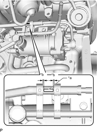
*a Paint Mark *b 0 to 2 mm (0 to 0.0787 in.) Install the fuel pipe clamp to the fuel filter assembly and No. 3 fuel pipe.
Note
Be careful that the fuel pipe clamp and No. 4 fuel pipe sub-assembly do not interfere with each other.
Tech Tips
Make sure the fuel pipe clamp is oriented as shown in the illustration.
-
-
INSTALL NO. 4 FUEL PIPE SUB-ASSEMBLY (w/ DPF)
-
Temporarily install the No. 4 fuel pipe sub-assembly and 2 new gaskets with the 2 union bolts and bolt.
-
Union Bolt 
Bolt Tighten the 2 union bolts and bolts in the order shown in the illustration.
- Torque:
- for union bolt
- 42 N*m { 428 kgf*cm, 31 ft.*lbf }
- for bolt
- 10 N*m { 102 kgf*cm, 7 ft.*lbf }
-
Connect the No. 4 fuel pipe sub-assembly to the No. 1 fuel pipe.
-
-
INSTALL WIRING HARNESS CLAMP BRACKET
-
Install the wiring harness clamp bracket with the bolt.
- Torque:
- 10 N*m { 102 kgf*cm, 7 ft.*lbf }
-
Attach the 2 wire harness clamps.
-
Connect the diesel throttle body assembly connector and pre-stroke control valve connector.
-
-
INSTALL NO. 2 FUEL PIPE
-
Connect the No. 2 fuel pipe and with the bolt.
- Torque:
- 10 N*m { 102 kgf*cm, 7 ft.*lbf }
-
-
INSTALL ENGINE OIL LEVEL DIPSTICK GUIDE
-
Apply a light coat of engine oil to a new O-ring.
-
Install the O-ring to the engine oil level dipstick guide.
-
Install the engine oil level dipstick guide with the bolt.
- Torque:
- 10 N*m { 102 kgf*cm, 7 ft.*lbf }
-
Connect the vacuum hose to the intake manifold.
-
Install the engine oil level dipstick.
-
w/ DPF and No. 2 Fuel Pipe Clamp:
Attach the No. 2 fuel pipe clamp to the engine oil level dipstick guide.
-
-
INSTALL EGR VALVE ADAPTER (w/o EGR Cooler)
-
Install the EGR pipe stay to the EGR valve adapter with the 2 bolts.
- Torque:
- 25 N*m { 255 kgf*cm, 18 ft.*lbf }
-
Temporarily install the EGR valve adapter to the intake manifold with the 4 bolts.
-
Tighten the 4 bolts in the order shown in the illustration.
Note
Make sure to tighten the bolts in the correct order.
- Torque:
- 21 N*m { 214 kgf*cm, 15 ft.*lbf }
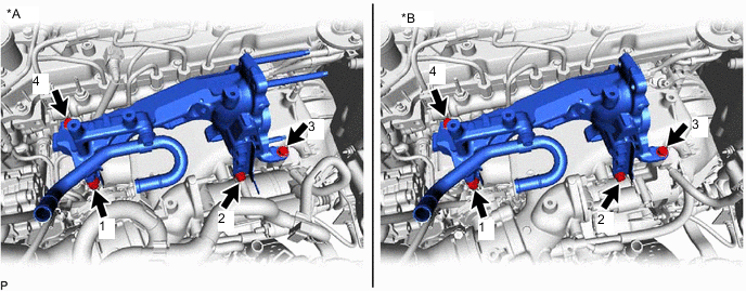
*A w/ EGR System *B w/o EGR System -
w/ EGR System:
Using an E8 "TORX" socket wrench, install 2 new stud bolts to the exhaust manifold.
- Torque:
- 10 N*m { 102 kgf*cm, 7 ft.*lbf }
-
w/ EGR System:
Install 2 new gaskets and the No. 1 EGR pipe sub-assembly to the exhaust manifold, electric EGR control valve assembly and No. 1 vacuum transmitting pipe sub-assembly with the bolt and 4 new nuts.
- Torque:
- for bolt
- 10 N*m { 102 kgf*cm, 7 ft.*lbf }
- for nut
- 29 N*m { 296 kgf*cm, 21 ft.*lbf }
-
w/ EGR System:
-
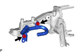
Connect the No. 4 water by-pass pipe sub-assembly to the intake manifold with the 2 bolts.
- Torque:
- 10 N*m { 102 kgf*cm, 7 ft.*lbf }
-
Connect the water hose to the EGR valve adapter, and slide the clamp to secure the hose.
-
Connect the No. 7 water by-pass hose to the EGR pipe stay, and slide the clamp to secure the hose.
-
-
w/o EGR System:
-
Connect the No. 4 water by-pass pipe sub-assembly to the intake manifold with the 2 bolts.
- Torque:
- 10 N*m { 102 kgf*cm, 7 ft.*lbf }
-
Connect the No. 7 water by-pass hose to the EGR pipe stay, and slide the clamp to secure the hose.
-
-
w/ EGR System:
-
Install the No. 3 water by-pass pipe sub-assembly to the EGR valve adapter with the 2 bolts.
- Torque:
- 10 N*m { 102 kgf*cm, 7 ft.*lbf }
-
Connect the No. 8 water by-pass hose to the No. 3 water by-pass pipe sub-assembly, and slide the clamp to secure the hose.
-
-
w/o EGR System:
Install the No. 3 water by-pass pipe sub-assembly to the EGR valve adapter with the 2 bolts.
- Torque:
- 10 N*m { 102 kgf*cm, 7 ft.*lbf }
-
Connect the No. 4 fuel hose to the No. 3 water by-pass pipe sub-assembly.
-
-
INSTALL ELECTRIC EGR CONTROL VALVE ASSEMBLY (w/ EGR System without EGR Cooler)
-
INSTALL EGR COOLER SUB-ASSEMBLY AND NO. 2 EGR VALVE ASSEMBLY WITH ELECTRIC EGR CONTROL VALVE ASSEMBLY (w/ EGR System with EGR Cooler)
-
CONNECT CABLE TO NEGATIVE BATTERY TERMINAL
Note
When disconnecting the cable, some systems need to be initialized after the cable is reconnected.
-
ADD ENGINE COOLANT
-
BLEED AIR FROM FUEL SYSTEM
-
INSPECT FOR FUEL LEAK
-
INSPECT FOR COOLANT LEAK
-
INSPECT FOR OIL LEAK
-
INSPECT ENGINE OIL LEVEL