INTAKE SYSTEM ON-VEHICLE INSPECTION
CAUTION / NOTICE / HINT
The necessary procedures (adjustment, calibration, initialization, or registration) that must be performed after parts are removed, installed, or replaced during the air leaks from intake system removal/installation are shown below.
| Replacement Part or Procedure | Necessary Procedures | Effect/Inoperative when not Performed | Link |
|---|---|---|---|
| Air leaks from intake system | Inspection after repair | Poor idle, engine start, etc. |
CAUTION:
To prevent injury due to contact with an operating fan and generator V-belt or cooling fan, keep your hand sand clothing away from the fan and generator V-belt and cooling fans when working in the engine compartment with the engine running.
PROCEDURE
-
INSPECT INTAKE SYSTEM
CAUTION:
To prevent injury due to contact with an operating fan and generator V-belt or cooling fan, keep your hand sand clothing away from the fan and generator V-belt and cooling fans when working in the engine compartment with the engine running.
Tech Tips
Perform "Inspection After Repair" after repairing air leaks in the intake system.
-
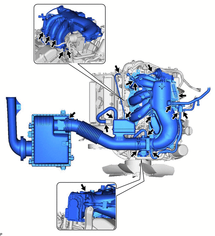
Check that there is no air suction at the pints shown in the illustration.
-
-
CHECK INTAKE AIR CONTROL FUNCTION
-
Warm up the engine.
-
Turn the ignition switch off.
-
Connect the GTS to the DLC3.
-
Start the engine.
-
Turn the GTS on.
-
Enter the following menus: Powertrain / Engine / Active Test / Activate the VSV for Intake Control.
Powertrain > Engine > Active TestTester Display Activate the VSV for Intake Control -
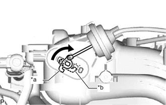
*a OFF (Vent) *b ON (Seal) Check that the VSV (for ACIS) is ON (seal) under either of the following conditions.
-
Depressing the accelerator pedal to obtain a throttle valve opening angle of 60°.
-
Racing the engine above 4700 rpm.
-
-
Check that the VSV (for ACIS) is OFF (vent) under either of the following conditions.
-
The engine is idling.
-
Releasing the accelerator pedal while under the VSV (for ACIS) ON condition.
If the result is not as specified, inspect the intake air control valve, intake air surge tank and VSV (for ACIS) for normal operation. Replace malfunctioning parts as necessary.
-
-
-
CHECK INTAKE AIR CONTROL VALVE OPERATION
-
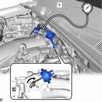
*a Vacuum Gauge Using a 3-way connector, connect a vacuum gauge to the actuator hose.
-
Start the engine.
-
While the engine is idling, check that the vacuum gauge needle momentarily fluctuates up to approximately 40 kPa (300 mmHg, 11.8 in.Hg) (the actuator rod is pulled out).
-
Rapidly depress the accelerator pedal to the fully depressed position and check that the vacuum gauge needle points to 0 kPa (0 mmHg, 0 in.Hg) (the actuator rod is returned).
-
Remove the vacuum gauge and connect the vacuum hose to the actuator.
-
-
INSPECT INTAKE AIR CONTROL VALVE
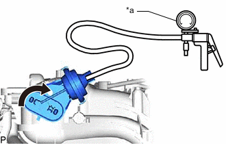
*a Vacuum Pump
-
Inspect the diaphragm.
-
Using a vacuum pump, apply a vacuum of 27 kPa (203 mmHg, 7.97 in.Hg). Check that the lever moves.
If the result is not as specified, replace the intake air surge tank.
-
-