EGR VALVE INSTALLATION
PROCEDURE
-
INSTALL NO. 2 EGR VALVE ASSEMBLY
-
Using an E8 "TORX" socket wrench, install the 4 stud bolts to the No. 2 EGR valve assembly.
- Torque:
- 10 N*m { 102 kgf*cm, 7 ft.*lbf }
-
Install a new gasket and the No. 2 EGR valve assembly to the No. 1 EGR cooler with the 4 bolts.
- Torque:
- 25 N*m { 255 kgf*cm, 18 ft.*lbf }
-
-
INSTALL EGR VALVE ADAPTER
-
Install a new gasket and the EGR valve adapter to the No. 2 EGR valve assembly with the 2 bolts.
- Torque:
- 25 N*m { 255 kgf*cm, 18 ft.*lbf }
-
-
INSTALL NO. 1 EGR COOLER AND NO. 2 EGR VALVE ASSEMBLY
-
Temporarily install the No. 1 EGR cooler and No. 2 EGR valve assembly to the intake manifold with the 4 bolts.
-
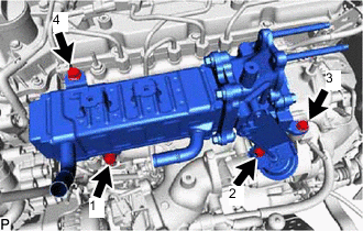
Tighten the 4 bolts in the order shown in the illustration.
Note
Make sure to tighten the bolts in the order.
- Torque:
- 21 N*m { 214 kgf*cm, 15 ft.*lbf }
-
-
INSTALL VACUUM CONTROL VALVE SET
-
Install the vacuum control valve set to the intake manifold with the 2 bolts.
- Torque:
- 10 N*m { 102 kgf*cm, 7 ft.*lbf }
-
Connect the 2 vacuum hoses to the No. 2 vacuum transmitting pipe sub-assembly and No. 2 EGR valve assembly.
-
Install the engine wire bracket with the bolt.
- Torque:
- 18.5 N*m { 189 kgf*cm, 14 ft.*lbf }
-
-
INSTALL NO. 1 EGR PIPE SUB-ASSEMBLY (w/o DPF)
-
Using an E8 "TORX" socket wrench, install 2 new stud bolts to the exhaust manifold.
- Torque:
- 10 N*m { 102 kgf*cm, 7 ft.*lbf }
-
Install 2 new gaskets and the No. 1 EGR pipe sub-assembly to the exhaust manifold and EGR valve adapter with 4 new nuts.
- Torque:
- 29 N*m { 296 kgf*cm, 21 ft.*lbf }
-
Connect the No. 1 EGR pipe sub-assembly to the vacuum transmitting pipe sub-assembly with the bolt.
- Torque:
- 10 N*m { 102 kgf*cm, 7 ft.*lbf }
-
-
INSTALL EGR PIPE WITH COOLER SUB-ASSEMBLY (w/ DPF)
-
Using an E8 "TORX" socket wrench, install 2 new stud bolts to the exhaust manifold.
- Torque:
- 10 N*m { 102 kgf*cm, 7 ft.*lbf }
-
Install 2 new gaskets and the EGR pipe with cooler sub-assembly to the exhaust manifold and EGR valve adapter with 4 new nuts.
- Torque:
- 29 N*m { 296 kgf*cm, 21 ft.*lbf }
-
Connect the EGR pipe with cooler sub-assembly to the vacuum transmitting pipe sub-assembly with the bolt.
- Torque:
- 10 N*m { 102 kgf*cm, 7 ft.*lbf }
-
-
CONNECT NO. 4 WATER BY-PASS PIPE SUB-ASSEMBLY
-
Connect the No. 4 water by-pass pipe sub-assembly to the intake manifold with the 2 bolts.
- Torque:
- 10 N*m { 102 kgf*cm, 7 ft.*lbf }
-
Connect the water hose to the No. 2 EGR valve assembly, and slide the clamp to secure the hose.
-
Connect the No. 7 water by-pass hose to the No. 1 EGR cooler, and slide the clamp to secure the hose.
-
w/ DPF:
Connect the No. 17 water by-pass hose to the No. 1 EGR pipe sub-assembly, and slide the clamp to secure the hose.
-
-
INSTALL NO. 3 WATER BY-PASS PIPE SUB-ASSEMBLY
-
Install the No. 3 water by-pass pipe sub-assembly to the No. 1 EGR cooler with the 2 bolts.
- Torque:
- 10 N*m { 102 kgf*cm, 7 ft.*lbf }
-
Connect the No. 8 water by-pass hose to the No. 3 water by-pass pipe sub-assembly, and slide the clamp to secure the hose.
-
Connect the No. 4 fuel hose to the No. 3 water by-pass pipe sub-assembly.
-
-
INSTALL ELECTRIC EGR CONTROL VALVE ASSEMBLY
-
Install a new gasket and the electric EGR control valve assembly to the No. 2 EGR valve assembly with the 2 bolts.
- Torque:
- 25 N*m { 255 kgf*cm, 18 ft.*lbf }
-
Connect the No. 9 water by-pass hose to the electric EGR control valve assembly, and slide the clamp to secure the hose.
-
Attach the clamp and connect the connector to the common rail assembly.
-
-
INSTALL NO. 2 EGR PIPE
-
Install 2 new gaskets and No. 2 EGR pipe to the electric EGR control valve assembly and the intake manifold with the 4 nuts.
- Torque:
- 29 N*m { 296 kgf*cm, 21 ft.*lbf }
-
-
INSTALL EGR VALVE BRACKET
-
Install the EGR valve bracket to the electric EGR control valve assembly and intake manifold with the bolt and nut.
- Torque:
- 21 N*m { 214 kgf*cm, 15 ft.*lbf }
-
-
CONNECT ENGINE WIRE
-
Connect the connector to the vacuum control valve set.
-
Attach the clamp and install the bolt.
- Torque:
- 18.5 N*m { 189 kgf*cm, 14 ft.*lbf }
-
Attach the clamp and connect the connector to the power steering oil pressure switch.
-
w/o DPF:
-
Attach the clamp and install the bolt.
- Torque:
- 12.5 N*m { 127 kgf*cm, 9 ft.*lbf }
-
Connect the connector to the sensor wire of the common rail assembly.
-
Connect the connector to the glow plug connector.
-
Connect the connector to the electric EGR control valve assembly.
-
Connect the 4 connectors to the 4 injector assemblies.
-
Connect the connector to the camshaft position sensor.
-
-
w/ DPF:
-
Attach the 2 clamps and install the bolt.
- Torque:
- 12.5 N*m { 127 kgf*cm, 9 ft.*lbf }
-
Connect the connector to the sensor wire of the common rail assembly.
-
Connect the connector to the glow plug connector.
-
Connect the connector to the electric EGR control valve assembly.
-
Connect the 4 connectors to the 4 injector assemblies.
-
Connect the connector to the camshaft position sensor.
-
Connect the connector to the exhaust fuel addition injector assembly.
-
Connect the 3 connectors to the 3 exhaust gas temperature sensors.
-
Connect the connector to the differential pressure sensor.
-
-
Attach the 2 clamps and connect the 2 connectors to the turbocharger sub-assembly.
-
-
INSTALL NO. 1 UREA TANK FILLER PIPE SUPPORT (w/ Urea SCR System)
-
Install the No. 1 urea tank filler pipe support to the body with the 2 bolts.
- Torque:
- 13 N*m { 133 kgf*cm, 10 ft.*lbf }
-
-
CONNECT UREA TANK FILLER PIPE ASSEMBLY (w/ Urea SCR System)
-
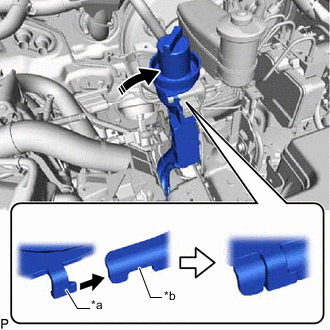
*a Protrusion *b Notch Align the protrusion of the urea tank filler pipe assembly with the notches the No. 1 urea tank filler pipe support.
-
Attach the claw and and connect the urea tank filler pipe assembly to the No. 1 urea tank filler pipe support.
-
-
CONNECT FUEL FILTER ASSEMBLY
-
Connect the fuel filter assembly to the fuel filter support.
-
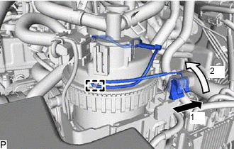
Attach the clamp and slide the lead wire as shown in the illustration to install it.
-
-
INSTALL NO. 2 ENGINE COVER BRACKET
-
Install the No. 2 engine cover bracket to the No. 3 water by-pass pipe sub-assembly and No. 2 EGR valve assembly with the 2 bolts.
- Torque:
- 10 N*m { 102 kgf*cm, 7 ft.*lbf }
-
-
INSTALL NO. 2 HOSE TO HOSE TUBE
-
Install the No. 2 hose to hose tube to the cylinder head cover sub-assembly and hose bracket with the 2 bolts.
- Torque:
- 10 N*m { 102 kgf*cm, 7 ft.*lbf }
-
Connect the union to check valve hose to the vacuum pump assembly, and slide the clamp to secure the hose.
-
Connect the union to connector tube hose to the No. 1 hose to hose tube, and slide the clamp to secure the hose.
-
-
INSTALL TURBO PRESSURE SENSOR
-
Install the turbo pressure sensor to the No. 3 water by-pass pipe sub-assembly with the bolt.
- Torque:
- 10 N*m { 102 kgf*cm, 7 ft.*lbf }
-
Connect the connector to the turbo pressure sensor.
-
-
INSTALL GAS FILTER
-
Install the gas filter to the gas filter bracket.
-
Connect the 2 vacuum hoses to the turbo pressure sensor and intake manifold.
-
-
INSTALL NO. 2 WATER BY-PASS PIPE
-
w/o Heater:
-
Install the No. 2 water by-pass pipe to the cylinder head cover sub-assembly, No. 3 water by-pass pipe sub-assembly and No. 2 engine cover bracket with the 3 bolts.
- Torque:
- 10 N*m { 102 kgf*cm, 7 ft.*lbf }
-
Connect the No. 16 water by-pass hose to the No. 1 EGR cooler, and slide the clamp to secure the hose.
-
Connect the No. 15 water by-pass hose to the water by-pass pipe, and slide the clamp to secure the hose.
-
-
w/ Heater:
-
Install the No. 2 water by-pass pipe to the cylinder head cover sub-assembly, No. 3 water by-pass pipe sub-assembly and No. 2 engine cover bracket with the 4 bolts.
- Torque:
- 10 N*m { 102 kgf*cm, 7 ft.*lbf }
-
Connect the No. 16 water by-pass hose to the No. 1 EGR cooler, and slide the clamp to secure the hose.
-
Connect the 2 heater hoses to the No. 2 water by-pass pipe, and slide the 2 clamps to secure the 2 hoses.
-
Connect the No. 15 water by-pass hose to the water by-pass pipe, and slide the clamp to secure the hose.
-
w/o Viscous Heater:
Connect the No. 2 water by-pass pipe to the No. 13 water by-pass hose, and slide the clamp to secure the hose.
-
w/ Viscous Heater:
Connect the No. 2 water by-pass pipe to the water hose sub-assembly, and slide the clamp to secure the hose.
-
w/ DPF:
Connect the No. 18 water by-pass hose to the EGR pipe with cooler sub-assembly, and slide the clamp to secure the hose.
-
-
-
INSTALL DIESEL THROTTLE BODY ASSEMBLY
-
ADD ENGINE COOLANT
-
INSPECT FOR COOLANT LEAK