CAUTION / NOTICE / HINT
The necessary procedures (adjustment, calibration, initialization, or registration) that must be performed after parts are removed, installed, or replaced during the throttle body with motor assembly removal/installation are shown below.
| Replacement Part or Procedure | Necessary Procedures | Effects/Inoperative when not Performed | Link |
|---|---|---|---|
| Replacement of throttle body with motor assembly | Inspection After Repair | Poor idle, engine start, etc. | |
| Cleaning the deposits from the throttle body with motor assembly |
PROCEDURE
- Click here
REMOVE ENGINE ASSEMBLY
- Click here
INSTALL ENGINE TO ENGINE STAND
- Click here
REMOVE IGNITION COIL ASSEMBLY
- Click here
REMOVE SPARK PLUG
- Click here
REMOVE PCV PIPE
- Click here
REMOVE THROTTLE BODY WITH MOTOR ASSEMBLY
- Click here
REMOVE FUEL DELIVERY PIPE
- Click here
REMOVE FUEL INJECTOR ASSEMBLY
- Click here
REMOVE INTAKE MANIFOLD
- Click here
REMOVE GENERATOR ASSEMBLY
- Click here
REMOVE NO. 1 COMPRESSOR MOUNTING BRACKET (w/ Air Conditioning System)
- Click here
REMOVE V-RIBBED BELT TENSIONER ASSEMBLY
- Click here
REMOVE WATER INLET
- Click here
REMOVE THERMOSTAT
- Click here
REMOVE NO. 1 IDLER PULLEY SUB-ASSEMBLY
- Click here
REMOVE NO. 1 WATER BY-PASS PIPE
- Click here
REMOVE OIL FILLER CAP SUB-ASSEMBLY
- Click here
REMOVE CAMSHAFT POSITION SENSOR (for Intake Side)
- Click here
REMOVE CAMSHAFT POSITION SENSOR (for Exhaust Side)
- Click here
REMOVE CAMSHAFT TIMING OIL CONTROL VALVE ASSEMBLY (for Exhaust Side)
- Click here
REMOVE CYLINDER HEAD COVER SUB-ASSEMBLY
-
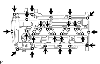
Remove the 21 bolts, 2 nuts, 2 plate washers, 2 seal washers and cylinder head cover sub-assembly.
-
Remove the cylinder head cover gasket from the cylinder head cover sub-assembly.
-
Remove the No. 1 camshaft bearing cap oil hole gasket from the cylinder head cover connector sub-assembly.
-
- Click here
REMOVE CRANKSHAFT PULLEY
-
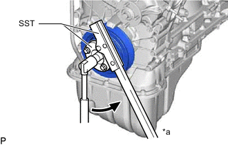
*a Hold 
Turn Using SST, hold the crankshaft pulley and loosen the pulley bolt until 2 or 3 threads are screwed into the crankshaft.
09213-54015 91651-60855 09330-00021 -
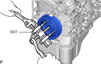
Using SST and the pulley bolt, remove the crankshaft pulley.
09950-50013 09951-05010 09952-05010 09953-05010 09954-05021 Tip:Apply lubricant to the threads and end of SST.
-
- Click here
REMOVE OIL PAN COVER SILENCER
-
Remove the 4 oil pan plugs and oil pan cover silencer.
-
- Click here
REMOVE NO. 2 OIL PAN SUB-ASSEMBLY
-
Remove the oil pan drain plug and gasket.
-
Remove the 16 bolts, 4 adjusting screws and 2 nuts.
-
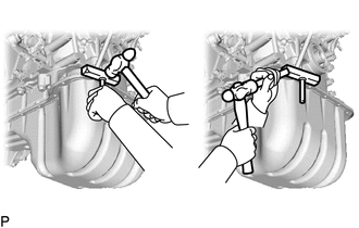
Insert the blade of an oil pan seal cutter between the No. 1 oil pan sub-assembly and No. 2 oil pan sub-assembly. Cut through the applied sealer and remove the No. 2 oil pan sub-assembly.
Note:Be careful not to damage the contact surfaces of the No. 1 oil pan sub-assembly and No. 2 oil pan sub-assembly.
-
- Click here
REMOVE OIL STRAINER SUB-ASSEMBLY
-
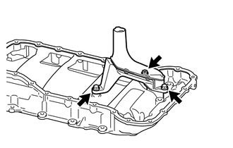
Remove the 2 bolts, nut, oil strainer sub-assembly and gasket.
-
- Click here
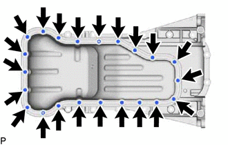
REMOVE OIL PAN SUB-ASSEMBLY
-
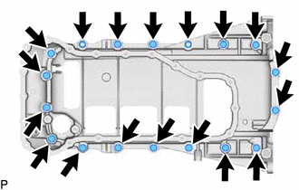
Remove the 16 bolts and 2 nuts.
-
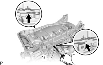
*a Protective Tape Remove the oil pan sub-assembly by prying between the oil pan sub-assembly and cylinder block sub-assembly with a screwdriver.
Note:Be careful not to damage the contact surfaces of the cylinder block sub-assembly and oil pan sub-assembly.
Tip:Tape the screwdriver tip before use.
-
- Click here
REMOVE CRANKSHAFT POSITION SENSOR
- Click here
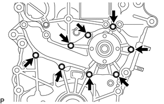
REMOVE TIMING CHAIN COVER SUB-ASSEMBLY
-
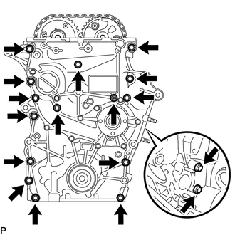
w/ Air Conditioning System
Remove the 16 bolts and nut shown in the illustration.
-
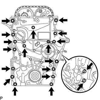
w/ Air Conditioning System
Remove the 18 bolts and nut shown in the illustration.
-
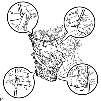
*a Protective Tape Remove the timing chain cover sub-assembly by prying between the timing chain cover sub-assembly and cylinder head sub-assembly or cylinder block sub-assembly with a screwdriver.
Note:Be careful not to damage the contact surfaces of the cylinder head sub-assembly, cylinder block sub-assembly and timing chain cover sub-assembly.
Tip:Tape the screwdriver tip before use.
-
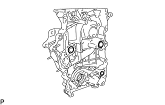
Remove the 3 O-rings.
-
- Click here
REMOVE ENGINE WATER PUMP ASSEMBLY
-
Remove the 8 bolts, engine water pump assembly and gasket.
-
- Click here
REMOVE TIMING CHAIN CASE OIL SEAL
-
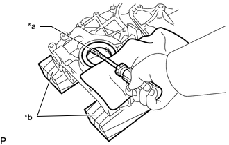
*a Protective Tape *b Wooden Block Place the timing chain cover sub-assembly on wooden blocks.
-
Using a screwdriver pry out the timing chain case oil seal.
Tip:Tape the screwdriver tip before use.
-