ENGINE OIL COOLER REMOVAL
CAUTION / NOTICE / HINT
The necessary procedures (adjustment, calibration, initialization, or registration) that must be performed after parts are removed, installed, or replaced during the oil cooler assembly removal/installation are shown below.
| Replacement Part or Procedure | Necessary Procedures | Effects/Inoperative when not Performed | Link |
|---|---|---|---|
| Replacement of fuel supply pump assembly | Supply Pump Initialization | Engine startability | |
| Replacement of timing belt | Mode reset operation |
|
Note
-
When replacing the parts in the following chart (A), replace the No. 1 injection pipe sub-assembly, No. 2 injection pipe sub-assembly, No. 3 injection pipe sub-assembly, No. 4 injection pipe sub-assembly and/or fuel inlet pipe sub-assembly with new ones.
Replaced Parts (A) Pipes Requiring New Replacement
-
Injector assembly (including shuffling the injector assemblies between the cylinders)
-
Common rail assembly
-
Cylinder head sub-assembly
-
No. 1 injection pipe sub-assembly
-
No. 2 injection pipe sub-assembly
-
No. 3 injection pipe sub-assembly
-
No. 4 injection pipe sub-assembly
-
Supply pump assembly
-
Common rail assembly
-
Cylinder block sub-assembly
-
Cylinder head sub-assembly
-
Cylinder head gasket
-
Timing Gear Case Assembly
Fuel inlet pipe sub-assembly -
-
After removing the No. 1 injection pipe sub-assembly, No. 2 injection pipe sub-assembly, No. 3 injection pipe sub-assembly, No. 4 injection pipe sub-assembly and fuel inlet pipe sub-assembly, clean them with a brush and compressed air.
PROCEDURE
-
REMOVE NO. 1 ENGINE UNDER COVER ASSEMBLY
-
DRAIN ENGINE COOLANT
-
DRAIN ENGINE OIL
-
REMOVE FUEL SUPPLY PUMP ASSEMBLY
-
REMOVE COMMON RAIL ASSEMBLY
-
REMOVE STARTER ASSEMBLY
-
REMOVE OIL FILTER SUB-ASSEMBLY
-
REMOVE OIL COOLER COVER SUB-ASSEMBLY
-
Disconnect the connector from the engine oil pressure switch assembly.
-
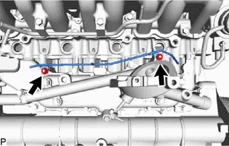
Remove the 2 nuts and disconnect the No. 2 vacuum transmitting pipe sub-assembly from the oil cooler cover sub-assembly.
-
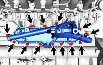
Remove the 13 bolts, oil cooler cover sub-assembly and gasket from the cylinder block sub-assembly.
-
-
REMOVE OIL COOLER ASSEMBLY
-
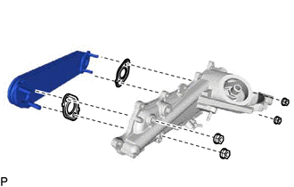
Loosen the 4 nuts.
-
Partially tap out the oil cooler assembly by tapping each nut head with a plastic-faced hammer.
-
Remove the 4 nuts, oil cooler assembly and 2 gaskets from the oil cooler cover sub-assembly.
-