PROCEDURE
- Click here
INSTALL NO. 1 WATER BY-PASS PIPE
-
Install a new gasket and the No. 1 water by-pass pipe with the 2 nuts.
17.5 N*m 178 kgf*cm 13 ft.*lbf
-
- Click here
INSTALL NO. 1 IDLER PULLEY SUB-ASSEMBLY
- Click here
INSTALL NO. 1 COMPRESSOR MOUNTING BRACKET (w/ Air Conditioning System)
Note:Install the No. 1 compressor mounting bracket exactly as described in the procedures below to properly secure and prevent damage to the fan and generator V belt.
-
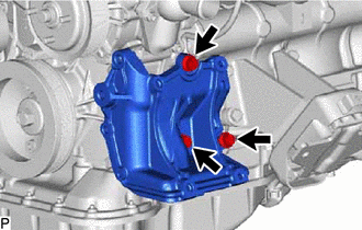
Temporarily install the No. 1 compressor mounting bracket with the 3 bolts.
Tip:Temporarily install the No. 1 compressor mounting bracket with the 3 bolts so that the bracket can be moved by hand.
-
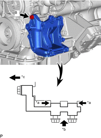
*a No Clearance *b Push *c Front Push the No. 1 compressor mounting bracket toward the cylinder block as shown in the illustration and tighten bolt B.
for bolt B 45 N*m 459 kgf*cm 33 ft.*lbf Tip:Make sure there is no clearance between the cylinder block and No. 1 compressor mounting bracket as shown in the illustration.
-
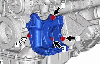

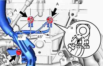
Bolt A 
Bolt C Uniformly tighten the 4 bolts in the order shown in the illustration.
for bolt A 45 N*m 459 kgf*cm 33 ft.*lbf for bolt C 24.5 N*m 250 kgf*cm 18 ft.*lbf
-
- Click here
INSTALL IDLE PULLEY ASSEMBLY (w/ Air Conditioning System)
-
Temporarily install the idle pulley assembly with the bolt.
Note:Do not use any tools.
-
Tighten the bolt.
44 N*m 449 kgf*cm 32 ft.*lbf
-
- Click here
INSTALL GENERATOR ASSEMBLY
- Click here
INSTALL IGNITION COIL ASSEMBLY
- Click here
INSTALL EXHAUST MANIFOLD
- Click here
INSTALL AIR SWITCHING VALVE ASSEMBLY (w/ Secondary Air Injection System)
- Click here
INSTALL NO. 4 INTAKE PIPE (w/ Secondary Air Injection System)
- Click here
INSTALL NO. 1 EXHAUST MANIFOLD HEAT INSULATOR (w/ Secondary Air Injection System)
- Click here
INSTALL NO. 1 EXHAUST MANIFOLD HEAT INSULATOR (w/o Secondary Air Injection System)
- Click here
INSTALL FRONT NO. 1 ENGINE MOUNTING BRACKET RH
-
Install the front No. 1 engine mounting bracket RH with the 4 bolts.
51 N*m 520 kgf*cm 38 ft.*lbf
-
- Click here
INSTALL FRONT NO. 1 ENGINE MOUNTING BRACKET LH
-
Install the front No. 1 engine mounting bracket LH with the 4 bolts.
51 N*m 520 kgf*cm 38 ft.*lbf
-
- Click here
INSTALL NO. 1 WATER BY-PASS HOSE
-
Connect the No. 1 water by-pass hose to the cylinder head sub-assembly, and slide the clamp to secure the hose.
-
- Click here
INSTALL HEATER HOSE
-
Connect the heater hose to the cylinder head sub-assembly and No. 1 water by-pass pipe, and slide the clamp to secure the hoses.
-
- Click here
INSTALL ENGINE WIRE
-
*a INCORRECT *b Do not Allow Wires to Overlap Connect the engine wire (engine ground wire) to the rear side of the engine assembly with the 2 bolts so that it is within the specified range shown in the illustration.
for bolt A 25 N*m 255 kgf*cm 18 ft.*lbf -
Connect the engine wire to the rear side of the engine assembly with the bolt.
for bolt B 30 N*m 306 kgf*cm 22 ft.*lbf -
Connect the connectors and clamps of the engine wire.
-
- Click here
INSTALL INTAKE MANIFOLD
- Click here
INSTALL PCV PIPE
-
Install the PCV pipe with the bolt.
18 N*m 184 kgf*cm 13 ft.*lbf -
Connect the PCV hose to the PCV valve sub-assembly and intake manifold.
-
- Click here
INSTALL PURGE VSV
- Click here
INSTALL FUEL DELIVERY PIPE WITH FUEL INJECTOR
- Click here
INSTALL THROTTLE BODY WITH MOTOR ASSEMBLY