CYLINDER BLOCK REPLACEMENT

PROCEDURE
-
REPLACE TIGHT PLUG
Tech Tips
If coolant leaks from a tight plug or a plug is corroded, replace it.
-
Remove the tight plugs.
-
Apply adhesive to new tight plugs.
Adhesive Toyota Genuine Adhesive 1324, Three Bond 1324 or equivalent Note
Do not start the engine for 1 hour after installation.
-
Using SST and a hammer, tap in the tight plugs as shown in the illustration.
Position A
- SST
- 09950-60010 ( 09951-00250 )
- 09950-70010 ( 09951-07100 )
Position B
- SST
- 09950-60010 ( 09951-00350 )
- 09950-70010 ( 09951-07100 )
Position C
- SST
- 09950-60010 ( 09951-00500 )
- 09950-70010 ( 09951-07100 )
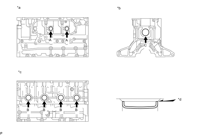
*a RH Side *b Rear Side *c LH Side *d Stops
-
-
REPLACE STRAIGHT PIN
Tech Tips
It is not necessary to remove a straight pin unless it is being replaced.
-
Remove the straight pins.
-
Using a plastic-faced hammer, tap in new straight pins to the cylinder block sub-assembly.
Standard protrusion height 14.5 mm (0.571 in.) or less 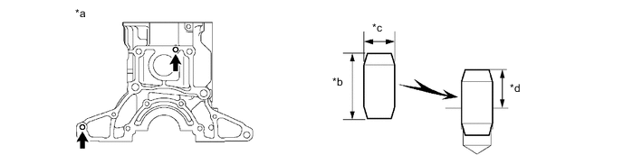
*a Rear Side *b 22 mm (0.866 in.) *c 10 mm (0.394 in.) *d Protrusion Height
-
-
REPLACE RING PIN
Tech Tips
It is not necessary to remove the ring pin unless it is being replaced.
-
Remove the ring pins.
-
Using a plastic-faced hammer, tap in new ring pins to the cylinder block sub-assembly.
Standard protrusion height 4.5 mm (0.177 in.) or less 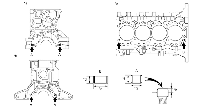
*a Front Side *b Rear Side *c Cylinder Head Sub-assembly Side *d 7 mm (0.276 in.) *e 14.5 mm (0.571 in.) *f 8 mm (0.315 in.) *g 11 mm (0.433 in.) *h Protrusion Height
-
-
REPLACE NO. 1 TAPER SCREW PLUG
Tech Tips
If a No. 1 taper screw plug is deformed or its threads are damaged, replace it.
-
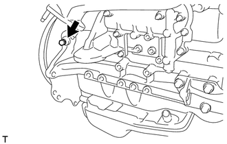
Remove the No. 1 taper screw plug.
-
Clean the cylinder block sub-assembly side hole and new No. 1 taper screw plug with non-residue solvent.
-
Apply adhesive to 2 or 3 threads of the No. 1 taper screw plug.
Adhesive Toyota Genuine Adhesive 1324, Three Bond 1324 or equivalent -
Install the No. 1 taper screw plug.
- Torque:
- 19.5 N*m { 199 kgf*cm, 14 ft.*lbf }
-
-
REPLACE CONNECTING ROD SMALL END BUSH
-
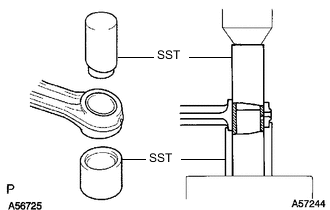
Using SST and a press, press out the connecting rod small end bush.
- SST
- 09222-54011 ( 09222-03016, 09222-03026, 09222-03021 )
-
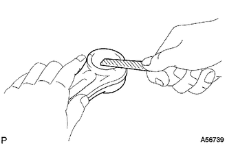
Using a round file, lightly file off any roughness from the small end of the connecting rod sub-assembly.
-
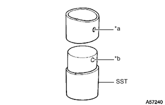
*a Oil Hole *b Ball Attach a new connecting rod small end bush to SST with the ball of SST inside the oil hole of the connecting rod small end bush.
- SST
- 09222-54011 ( 09222-03021 )
-
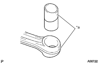
*a Oil Hole Align the oil holes of the connecting rod small end bush and connecting rod sub-assembly.
-
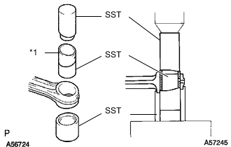
*1 Connecting Rod Small End Bush Using SST and a press, press in the connecting rod small end bush.
- SST
- 09222-54011 ( 09222-03016, 09222-03026, 09222-03021 )
-
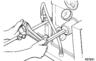
Using a pin hole grinder, hone the connecting rod small end bush to obtain the specified clearance between the connecting rod small end bush and piston pin.
Standard oil clearance 0.004 to 0.012 mm (0.0002 to 0.0005 in.) -
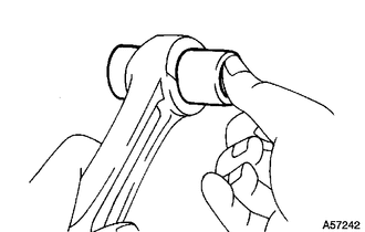
Check that the piston pin fits at normal room temperature.
-
Coat the piston pin with engine oil, and push it into the connecting rod with your thumb.
-