CYLINDER BLOCK DISASSEMBLY

PROCEDURE
-
REMOVE CYLINDER BLOCK OIL ORIFICE
-
Using a 6 mm hexagon socket wrench, remove the cylinder block oil orifice.
-
-
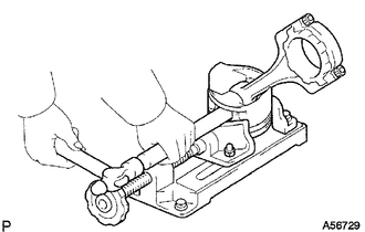
INSPECT CONNECTING ROD THRUST CLEARANCE
-
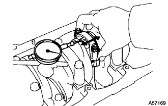
Using a dial indicator, measure the thrust clearance while moving the connecting rod sub-assembly back and forth.
Standard thrust clearance 0.08 to 0.3 mm (0.00315 to 0.0118 in.) Maximum thrust clearance 0.35 mm (0.0138 in.) If the thrust clearance is more than the maximum, replace the connecting rod sub-assembly. If necessary, replace the crankshaft.
-
-
INSPECT CONNECTING ROD OIL CLEARANCE
-
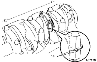
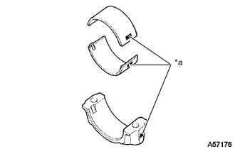
*a Matchmark Check the matchmarks on the connecting rod sub-assembly and connecting rod cap to ensure correct reassembly.
-
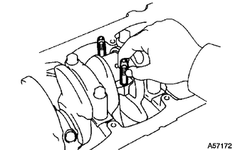
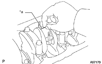
Remove the 2 connecting rod cap nuts.
-
Using a plastic-faced hammer, lightly tap the connecting rod bolts and lift off the connecting rod cap.
Tech Tips
Keep the connecting rod bearing and connecting rod cap together.
-
Cover the connecting rod bolts with a short piece of hose to protect the crankshaft from damage.
-
Clean the crank pin and connecting rod bearing.
-
Check the crank pin and connecting rod bearing for pitting and scratches.
If the crank pin or a connecting rod bearing is damaged, replace the connecting rod bearings. If necessary, grind or replace the crankshaft.
-
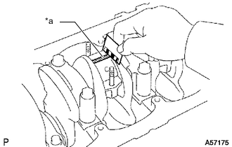
*a Plastigage Lay a strip of Plastigage across the crank pin.
-
Install the connecting rod cap.
Note
Do not turn the crankshaft.
-
Remove the 2 connecting rod nuts, connecting rod cap and lower connecting rod bearing.
-
*a Plastigage Measure the Plastigage at its widest point.
Standard Oil Clearance Item Specified Condition STD 0.036 to 0.064 mm (0.00142 to 0.00252 in.) U/S 0.25, U/S 0.50 0.033 to 0.079 mm (0.00130 to 0.00311 in.) Maximum oil clearance 0.1 mm (0.00394 in.) If the oil clearance is more than the maximum, replace the connecting rod bearings. If necessary, grind or replace the crankshaft.
-
*a Mark 1, 2 or 3 If using a standard connecting rod bearing, replace it with one that has the same number marked on the connecting rod cap. There are 3 sizes of standard connecting rod bearings, marked 1, 2 and 3 accordingly.
Standard Sized Bearing Center Wall Thickness Item Specified Condition Mark 1 1.478 to 1.482 mm (0.0582 to 0.0583 in.) Mark 2 1.482 to 1.486 mm (0.0583 to 0.0585 in.) Mark 3 1.486 to 1.490 mm (0.0585 to 0.0587 in.) -
Completely remove the Plastigage.
-
-
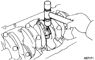
REMOVE PISTON AND CONNECTING ROD
-
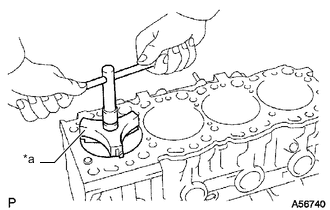
*a Ridge Reamer Using a ridge reamer, remove all the carbon from the top of the cylinder.
-
Cover the connecting rod bolts with a short piece of hose to protect the crankshaft from damage.
-
Push the piston, connecting rod and upper connecting rod bearing through the top of the cylinder block sub-assembly to remove them.
Tech Tips
-
Keep the connecting rod bearings, connecting rod and connecting rod cap together.
-
Arrange the piston and connecting rod sub-assemblies in the correct order.
-
Be sure to organize the removed piston and connecting rod in such a way that they can be reinstalled exactly as before.
-
-
-
REMOVE CONNECTING ROD BEARING
-
Remove the connecting rod bearings from the connecting rods and connecting rod caps.
Tech Tips
Arrange the removed parts in the correct order.
-
-
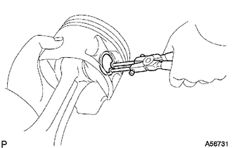
REMOVE PISTON RING SET
Tech Tips
Arrange the piston rings in the correct order.
-
Using a piston ring expander, remove the No. 1 piston ring and No. 2 piston ring.
-
Remove the oil ring and coil by hand.
-
-
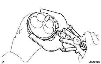
REMOVE PISTON WITH PIN SUB-ASSEMBLY
-
Using snap ring pliers, remove the 2 snap rings from the piston.
-
Gradually heat the piston to approximately 60°C (140°F).
-
Using a plastic-faced hammer and brass bar, lightly tap out the piston pin. Then remove the connecting rod sub-assembly.
Tech Tips
-
The piston and piston pin are a matched set.
-
Be sure to organize the removed pistons, piston pins, piston rings, connecting rod sub-assemblies and connecting rod bearings in such a way that the parts can be reinstalled exactly as before.
-
Arrange the pistons, piston pins, connecting rod sub-assemblies and connecting rod bearings in the correct order.
-
-
-
INSPECT CRANKSHAFT THRUST CLEARANCE
-
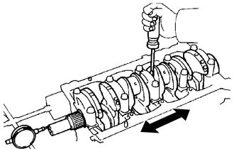
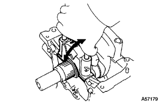
Using a dial indicator, measure the thrust clearance while prying the crankshaft back and forth with a screwdriver.
Standard thrust clearance 0.040 to 0.250 mm (0.00157 to 0.00984 in.) Maximum thrust clearance 0.3 mm (0.0118 in.) If the thrust clearance is more than the maximum, replace the thrust washers as a set.
Thrust Washer Thickness Item Specified Condition STD 2.430 to 2.480 mm (0.0957 to 0.0976 in.) O/S 0.125 2.493 to 2.543 mm (0.0981 to 0.100 in.) O/S 0.250 2.555 to 2.605 mm (0.101 to 0.103 in.)
-
-
INSPECT CRANKSHAFT OIL CLEARANCE
-
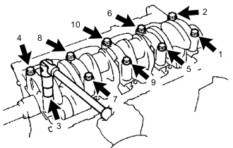
Uniformly loosen and remove the 10 crankshaft bearing cap bolts in several passes, in the sequence shown.
-
Using the removed crankshaft bearing cap bolts, pry the crankshaft bearing cap back and forth and remove the crankshaft bearing caps, lower crankshaft bearings and lower crankshaft thrust washers (No. 3 crankshaft bearing cap only).
Tech Tips
-
Keep the lower crankshaft bearing and crankshaft bearing cap together.
-
Be sure to organize the crankshaft bearing caps and lower crankshaft thrust washers (No. 3 crankshaft bearing only) in such a way that they can be reinstalled exactly as before.
-
-
Lift out the crankshaft.
-
Clean each main journal and crankshaft bearing.
-
Check each crankshaft journal and bearing for pitting and scratches.
If a journal or one of its crankshaft bearings is damaged, replace the crankshaft bearings for that journal. If necessary, grind or replace the crankshaft.
-
Place the crankshaft on the cylinder block sub-assembly.
-
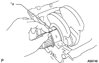
*a Plastigage Lay a strip of Plastigage across each journal.
-
Install the crankshaft bearing caps.
Note
Do not turn the crankshaft.
-
Remove the crankshaft bearing caps.
-
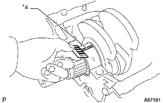
*a Plastigage 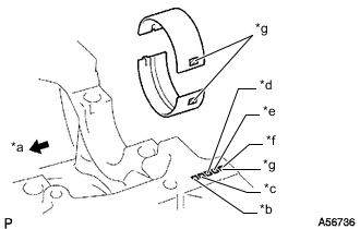
*a Front *b No. 1 *c No. 2 *d No. 3 *e No. 4 *f No. 5 *g Mark 1, 2 or 3 Measure the Plastigage at its widest point.
Standard Oil Clearance Item Specified Condition STD 0.034 to 0.065 mm (0.0013 to 0.0026 in.) U/S 0.25, U/S 0.50 0.033 to 0.079 mm (0.0013 to 0.0031 in.) Maximum oil clearance 0.1 mm (0.00394 in.) If the oil clearance is more than the maximum, replace the crankshaft bearings. If necessary, grind or replace the crankshaft.
Tech Tips
If using a standard crankshaft bearing, replace it with one that has the same number. If the number of the crankshaft bearing cannot be determined, select the correct crankshaft bearing by adding together the numbers imprinted on the cylinder block sub-assembly and crankshaft, and then selecting the crankshaft bearing with the same number as the total. There are 3 sizes of standard crankshaft bearings, marked 1, 2 and 3.
Standard Sized Bearing Center Wall Thickness Item Specified Condition Mark 1 1.979 to 1.983 mm (0.0779 to 0.0781 in.) Mark 2 1.983 to 1.987 mm (0.0781 to 0.0782 in.) Mark 3 1.987 to 1.991 mm (0.0782 to 0.0784 in.) -
Completely remove the Plastigage.
-
-
REMOVE CRANKSHAFT
-
Lift out the crankshaft.
-
Remove the upper crankshaft bearings and upper crankshaft thrust washers (No. 3 crankshaft bearing only) from the cylinder block sub-assembly.
Tech Tips
Arrange the crankshaft bearing caps, crankshaft bearings and crankshaft thrust washers (No. 3 crankshaft bearing only) in the correct order.
-
-
REMOVE NO. 1 OIL NOZZLE SUB-ASSEMBLY
-
Remove the 4 check valves and 4 No. 1 oil nozzle sub-assemblies.
-
-
REMOVE CYLINDER BLOCK WATER DRAIN COCK SUB-ASSEMBLY
-
Remove the cylinder block water drain cock sub-assembly from the cylinder block sub-assembly.
-
-
REMOVE STUD BOLT
Tech Tips
If a stud bolt is deformed or its threads are damaged, replace it.
-
Remove the stud bolts from the cylinder block sub-assembly.
-