CYLINDER HEAD REASSEMBLY

CAUTION / NOTICE / HINT
Tech Tips
-
Thoroughly clean all parts to be assembled.
-
Before installing the parts, apply fresh engine oil to all sliding and rotating surfaces.
-
Replace all gaskets and oil seals with new ones.
PROCEDURE
-
INSTALL STUD BOLT
Tech Tips
If a stud bolt is deformed or its threads are damaged, replace it.
-
Install the stud bolts to the cylinder head sub-assembly.
- Torque:
- for stud bolt A
- 6.0 N*m { 61 kgf*cm, 53 in.*lbf }
- for stud bolt B
- 12 N*m { 122 kgf*cm, 9 ft.*lbf }
- for stud bolt C
- 26 N*m { 265 kgf*cm, 19 ft.*lbf }
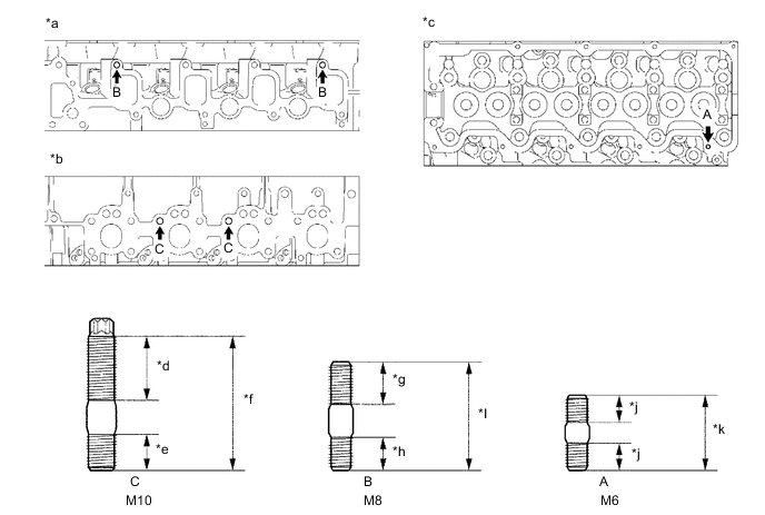
*a Intake Manifold Side *b Exhaust Manifold Side *c Cylinder Head Cover Sub-assembly Side *d 23.5 mm (0.925 in.) *e 12 mm (0.472 in.) *f 44.5 mm (1.75 in.) *g 14 mm (0.551 in.) *h 11 mm (0.433 in.) *i 36 mm (1.42 in.) *j 9 mm (0.354 in.) *k 25 mm (0.984 in.) - -
-
-
INSTALL SEMICIRCULAR PLUG
-
Remove any old packing (FIPG material).
-
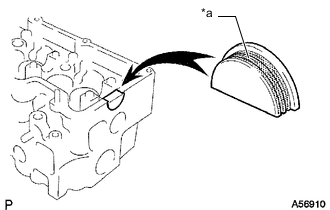
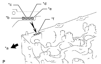
*a Seal Packing Apply seal packing to the semicircular plug as shown in the illustration.
Seal packing Toyota Genuine Seal Packing Black, Three Bond 1207B or equivalent Note
-
The semicircular plug must be installed within 3 minutes from the completion of applying the seal packing.
-
Prevent seal packing from being stuck to the camshaft thrust groove.
-
-
Install the semicircular plug to the cylinder head sub-assembly.
-
-
INSTALL COMBUSTION CHAMBER SUB-ASSEMBLY
-
*a Front *b No. 1 Combustion Chamber *c No. 2 Combustion Chamber *d No. 3 Combustion Chamber *e No. 4 Combustion Chamber *f Mark 1, 2 or 3 Select the number of shim, according to the table below.
Select a New Combustion Chamber Item Specified Condition Mark 1 5.91 to 5.94 mm (0.2327 to 0.2338 in.) Mark 2 5.94 to 5.97 mm (0.234 to 0.235 in.) Mark 3 5.97 to 6.0 mm (0.235 to 0.236 in.) -
*a Combustion Chamber Knock Pin Align the combustion chamber knock pin with the cylinder head sub-assembly notch.
-
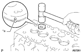
Using a plastic-faced hammer, tap in the combustion chamber sub-assembly.
-
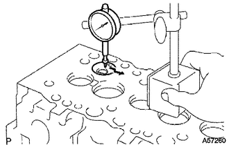
Using a dial indicator, check the combustion chamber protrusion.
Combustion chamber protrusion -0.03 to 0.03 mm (-0.00118 to 0.00118 in.) If the protrusion is less than the specification, adjust with shims.
If the protrusion is more than the specification, replace the combustion chamber sub-assembly and recheck the protrusion.
-
-
INSTALL INTAKE VALVE STEM OIL SEAL
-
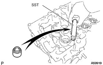
Using SST, push in a new intake valve stem oil seal to the intake valve guide bush.
- SST
- 09201-41020
-
-
INSTALL EXHAUST VALVE STEM OIL SEAL
-
Using SST, push in a new exhaust valve stem oil seal to the exhaust valve guide bush.
- SST
- 09201-41020
-
-
INSTALL INTAKE VALVE
-

*a 30 mm (1.18 in.) or more Apply a sufficient coat of engine oil to the tip area of the intake valve shown in the illustration.
-
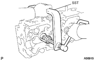
Install the intake valve, valve spring seat, inner compression spring and valve spring retainer to the cylinder head sub-assembly.
-
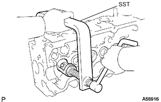
Using SST, compress the inner compression spring and install the 2 valve spring retainer locks to the valve stem.
- SST
- 09202-70020 ( 09202-00030 )
-
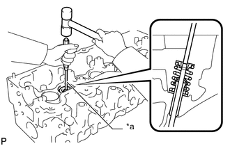
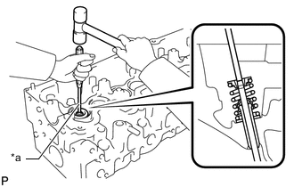
*a 5 mm Pin Punch Using a 5 mm pin punch and plastic-faced hammer, lightly tap the valve stem tip to ensure a proper fit.
Note
Be careful not to damage the valve stem tip.
-
-
INSTALL EXHAUST VALVE
-
*a 30 mm (1.18 in.) or more Apply a sufficient coat of engine oil to the tip area of the exhaust valve shown in the illustration.
-
Install the exhaust valve, valve spring seat, inner compression spring and valve spring retainer.
-
Using SST, compress the inner compression spring and install the 2 valve spring retainer locks to the valve stem to the cylinder head sub-assembly.
- SST
- 09202-70020 ( 09202-00030 )
-
*a 5 mm Pin Punch Using a 5 mm pin punch and plastic-faced hammer, lightly tap the valve stem tip to ensure a proper fit.
Note
Be careful not to damage the valve stem tip.
-
-
INSTALL VALVE LIFTER
-
Install the valve lifter and shim.
-
Check that the valve lifter rotates smoothly by hand.
-