ENGINE UNIT INSTALLATION

PROCEDURE
-
INSTALL OIL FILTER BRACKET SUB-ASSEMBLY
-
INSTALL OIL FILTER SUB-ASSEMBLY
-
INSTALL ENGINE OIL PRESSURE SWITCH ASSEMBLY
-
INSTALL EXHAUST MANIFOLD
-
INSTALL NO. 1 EXHAUST MANIFOLD HEAT INSULATOR
-
INSTALL VACUUM PUMP OIL OUTLET HOSE
-
Install the vacuum pump oil outlet hose to the oil pan sub-assembly and slide the clip to secure the hose.
-
-
INSTALL UNION
-
Clean the threads of the union and hole.
-
Apply adhesive to 2 or 3 threads at the end of union.
Adhesive Toyota Genuine Adhesive 1344, Three Bond 1344 or equivalent -
Install the union to the cylinder block sub-assembly.
- Torque:
- 28 N*m { 286 kgf*cm, 21 ft.*lbf }
-
-
INSTALL VACUUM PUMP OIL INLET HOSE
-
INSTALL PUMP BRACKET
-
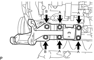
Install the pump bracket with the 6 bolts.
- Torque:
- for bolt A
- 57 N*m { 581 kgf*cm, 42 ft.*lbf }
- for bolt B
- 78 N*m { 795 kgf*cm, 58 ft.*lbf }
Bolt Length Item Length Thread Diameter Bolt A 26 mm (1.02 in.) 18 mm (0.709 in.) Bolt B 29 mm (1.14 in.) 19 mm (0.748 in.)
-
-
INSTALL NO. 1 FRONT ENGINE MOUNTING BRACKET RH
-
Install the No. 1 front engine mounting bracket RH with the 4 bolts.
- Torque:
- 49 N*m { 500 kgf*cm, 36 ft.*lbf }
-
-
INSTALL WATER HOSE JOINT
-
Clean the threads of the water hose joint and hole.
-
Apply adhesive to 2 or 3 threads at the end of the water hose joint.
Adhesive Toyota Genuine Adhesive 1324, Three Bond 1324 or equivalent -
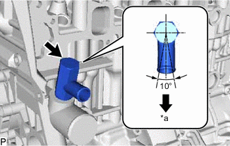
*a LH Side Install the water hose joint.
- Torque:
- 39 N*m { 398 kgf*cm, 29 ft.*lbf }
Note
Install the water hose joint within 3 minutes after applying adhesive.
-
Rotate the water hose joint clockwise to the position shown in the illustration.
Note
-
Do not rotate the water hose joint by more than 1 revolution (360°) after tightening the water hose joint to the specified torque.
-
Do not loosen the water hose joint after setting it correctly.
-
-
-
INSTALL WATER OUTLET HOUSING
-
Install a new gasket to the cylinder head sub-assembly.
-
Install the water outlet hosing with the 3 bolts.
- Torque:
- 19 N*m { 194 kgf*cm, 14 ft.*lbf }
-
-
INSTALL IDLE PULLEY ASSEMBLY WITH BRACKET (w/ Air Conditioning System)
-
Temporarily install the idle pulley assembly with bracket with the 3 bolts.
-
Tighten the 3 bolts.
- Torque:
- 46.6 N*m { 475 kgf*cm, 34 ft.*lbf }
-
-
INSTALL INTAKE MANIFOLD
-
INSTALL ENGINE OIL LEVEL DIPSTICK GUIDE
-
INSTALL CRANKSHAFT POSITION SENSOR
-
INSTALL ENGINE COOLANT TEMPERATURE SENSOR
-
INSTALL INJECTION PUMP ASSEMBLY
-
INSTALL INJECTION PUMP DRIVE PULLEY
-
INSTALL GLOW PLUG ASSEMBLY
-
INSTALL NOZZLE HOLDER AND NOZZLE SET
-
INSTALL NOZZLE LEAKAGE PIPE ASSEMBLY
-
INSTALL NO. 1 GLOW PLUG CONNECTOR
-
INSTALL INJECTION PIPE SUB-ASSEMBLY
-
INSTALL VENTURI ASSEMBLY
-
INSTALL INTAKE FLANGE
-
INSTALL CRANKSHAFT TIMING PULLEY
-
INSTALL TIMING BELT GUIDE
-
SET NO. 1 CYLINDER TO TDC/COMPRESSION
-
INSTALL TIMING BELT
-
INSTALL TIMING BELT COVER
-
INSTALL CRANKSHAFT PULLEY
-
INSTALL NO. 1 COMPRESSOR MOUNTING BRACKET (w/ Air Conditioning System)
-
Install the No. 1 compressor mounting bracket with the 4 bolts.
- Torque:
- 85.9 N*m { 876 kgf*cm, 63 ft.*lbf }
-