ENGINE ASSEMBLY INSTALLATION

PROCEDURE
-
INSTALL FRONT ENGINE MOUNTING INSULATOR
-
Install the 2 front engine mounting insulators to the 2 front engine mounting brackets with the 2 nuts.
- Torque:
- 46 N*m { 469 kgf*cm, 34 ft.*lbf }
-
-
INSTALL ENGINE WIRE
-
Install the engine wire to the engine assembly.
-
-
INSTALL NO. 2 ENGINE HANGER
-
REMOVE ENGINE FROM ENGINE STAND
Note
-
Pay attention to the angle of the sling device as the engine assembly or engine hangers may be damaged or deformed if the angle is incorrect.
-
With the exception of installing the engine assembly to an engine stand or removing the engine assembly from an engine stand, do not perform any work on the engine assembly while it is suspended, as doing so is dangerous.
-
Attach an engine sling device and hang the engine assembly with a chain block.
-
Remove the engine assembly from the engine stand.
-
-
INSTALL ENGINE ASSEMBLY
-
Slowly lower the engine assembly into the engine compartment.
-
Install the engine assembly to the body with the 4 bolts and 4 nuts.
- Torque:
- 42 N*m { 428 kgf*cm, 31 ft.*lbf }
Tech Tips
-
Make sure to tighten the side with the nut.
-
When installing a bolt with a claw (stopper), make sure that the claw (stopper) does not damage the body of the vehicle.
-
Remove the bolt and No. 2 engine hanger.
-
-
INSTALL FLYWHEEL HOUSING DUST SEAL
-
INSTALL REAR END PLATE
-
Install the rear end plate with the 2 bolts.
- Torque:
- 27 N*m { 275 kgf*cm, 20 ft.*lbf }
-
-
INSTALL FLYWHEEL SUB-ASSEMBLY
-
Clean the bolts and bolt holes.
-
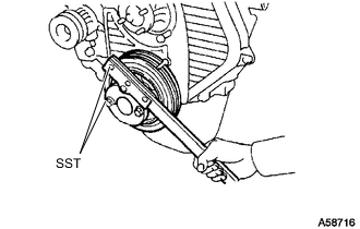
Using SST, hold the crankshaft.
- SST
- 09213-54015 ( 91651-60855 )
- 09330-00021
-
Apply adhesive to 2 or 3 threads of each of the bolts.
Adhesive Toyota Genuine Adhesive 1324, Three Bond 1324 or equivalent -
Temporarily install the flywheel sub-assembly to the crankshaft with the 8 bolts.
-
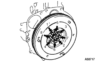
Tighten the 8 bolts uniformly in several steps in the order shown in the illustration.
- Torque:
- 122.5 N*m { 1249 kgf*cm, 90 ft.*lbf }
Note
Do not start the engine for at least 1 hour after installation.
-
-
INSTALL CLUTCH DISC ASSEMBLY
-
INSTALL CLUTCH COVER ASSEMBLY
-
INSTALL MANUAL TRANSMISSION UNIT ASSEMBLY
-
INSTALL PROPELLER WITH CENTER BEARING SHAFT ASSEMBLY
-
INSTALL FRONT PROPELLER SHAFT ASSEMBLY
-
INSTALL FRONT EXHAUST PIPE ASSEMBLY
-
INSTALL GENERATOR ASSEMBLY
-
INSTALL VANE PUMP ASSEMBLY
-
Temporarily install the vane pump assembly with the 2 bolts and nut.
-
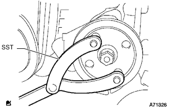
Install the vane pump pulley to the vane pump assembly shaft.
-
Using SST, hold the pulley and install the nut.
- SST
- 09960-10010 ( 09962-01000, 09963-01000 )
- Torque:
- 43 N*m { 438 kgf*cm, 32 ft.*lbf }
-
-
CONNECT COMPRESSOR ASSEMBLY WITH MAGNET CLUTCH (w/ Air Conditioning System)
-
Connect the compressor assembly with magnet clutch to the No. 1 compressor mounting bracket with the 4 bolts.
- Torque:
- 24.5 N*m { 250 kgf*cm, 18 ft.*lbf }
-
-
CONNECT FUEL HOSE
-
Connect the 2 fuel hoses to the injection pump assembly, and slide the 2 clamps to secure the hose.
-
-
CONNECT HEATER WATER HOSE ASSEMBLY
-
Install the bolt, connect the heater water hose assembly to the engine assembly, and slide the 2 clamps to secure the 2 hoses.
- Torque:
- 18.1 N*m { 185 kgf*cm, 13 ft.*lbf }
-
-
INSTALL BATTERY TRAY
-
INSTALL BATTERY
-
INSTALL BATTERY HOLD DOWN CLAMP
-
Install the battery clamp sub-assembly to the battery with the 2 nuts.
- Torque:
- 5.4 N*m { 55 kgf*cm, 48 in.*lbf }
-
-
CONNECT WIRE HARNESS
-
Connect the engine room main wire to the battery positive cable with the nut.
- Torque:
- 7.1 N*m { 72 kgf*cm, 63 in.*lbf }
-
Attach the clamp and connect the No. 2 engine wire with the 2 bolts.
- Torque:
- 14 N*m { 143 kgf*cm, 10 ft.*lbf }
-
Connect the 2 connectors to the engine room relay block sub-assembly.
-
Connect the wire to wire to the engine room relay block sub-assembly with the nut.
- Torque:
- 12.5 N*m { 127 kgf*cm, 9 ft.*lbf }
-
Attach the 2 clips and install the No. 1 relay block side cover to the engine room relay block sub-assembly.
-
Attach the 3 clips and install the No. 1 relay block upper cover to the engine room relay block sub-assembly.
-
-
INSTALL INTAKE PIPE
-
INSTALL AIR CLEANER CASE ASSEMBLY
-
Install the air cleaner case assembly with the 3 bolts.
- Torque:
- 6.0 N*m { 61 kgf*cm, 53 in.*lbf }
-
-
INSTALL AIR CLEANER FILTER ELEMENT SUB-ASSEMBLY
-
INSTALL AIR CLEANER CAP AND HOSE
-
Install the air cleaner cap and hose.
-
Attach the 4 clips.
-
Tighten the hose clamp.
- Torque:
- 4.0 N*m { 41 kgf*cm, 35 in.*lbf }
-
Connect the connector to the intake air temperature sensor and attach the 5 wire harness clamps.
-
-
CONNECT ENGINE WIRE
-
Pass the engine wire into the cabin.
-
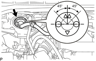
Attach the grommet to the body.
Tech Tips
Make sure the direction of the grommet is as shown in the illustration.
-
Attach the 2 wire harness clamps to connect the engine wire to the wire harness bracket.
-
Attach the 2 clamps and connect the 3 connectors to the instrument panel wire.
-
Install the ECM.
-
-
INSTALL GLOVE COMPARTMENT DOOR ASSEMBLY
-
INSTALL RADIATOR ASSEMBLY
-
INSTALL FAN AND GENERATOR V BELT
-
INSTALL COOLER COMPRESSOR V BELT (w/ Air Conditioning System)
-
INSTALL VANE PUMP V BELT
-
INSTALL HOOD SUB-ASSEMBLY
-
Install the hood sub-assembly to the 2 hood hinge assemblies with the 4 bolts.
- Torque:
- 13 N*m { 133 kgf*cm, 10 ft.*lbf }
-
Connect the washer nozzle hose to the hood sub-assembly.
-
-
ADD POWER STEERING FLUID
-
ADD MANUAL TRANSMISSION OIL
-
ADD ENGINE OIL
-
CONNECT CABLE TO NEGATIVE BATTERY TERMINAL
Note
When disconnecting the cable, some systems need to be initialized after the cable is reconnected.
-
BLEED AIR FROM FUEL SYSTEM
-
ADD ENGINE COOLANT
-
BLEED AIR FROM POWER STEERING SYSTEM
-
INSPECT POWER STEERING FLUID LEVEL
-
INSPECT FOR COOLANT LEAK
-
INSPECT FOR OIL LEAK
-
INSPECT FOR EXHAUST GAS LEAK
-
INSPECT FOR FUEL LEAK
-
CHECK ENGINE IDLE SPEED AND MAXIMUM SPEED
-
INSPECT ENGINE OIL LEVEL
-
INSTALL NO. 2 ENGINE UNDER COVER
- Torque:
- 28 N*m { 286 kgf*cm, 21 ft.*lbf }
-
INSTALL NO. 1 ENGINE UNDER COVER ASSEMBLY
- Torque:
- for M6 bolt
- 11.5 N*m { 117 kgf*cm, 8 ft.*lbf }
- for M8 bolt
- 28 N*m { 286 kgf*cm, 21 ft.*lbf }