CYLINDER HEAD GASKET INSTALLATION
PROCEDURE
-
INSTALL CYLINDER HEAD GASKET
-
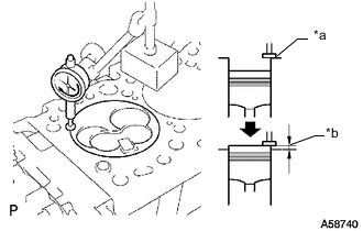
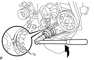
*a Measuring Tip *b Protrusion Check the piston protrusion for each cylinder.
-
Clean the cylinder block sub-assembly with solvent.
-
Set the piston of the cylinder to be measured to slightly before TDC.
-
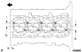
*a Measuring Point *b 25.0 mm (0.984 in.) 
Front Place a dial indicator on the cylinder block sub-assembly, and position the measuring tip as shown in the illustration.
-
Set the dial indicator at 0 mm (0 in.).
Tech Tips
Make sure that the measuring tip is square to the cylinder block sub-assembly gasket surface and piston head when taking the measurements.
-
Measure the protrusion of each cylinder at 2 places as shown in the illustration, making a total of 8 measurements.
-
For the piston protrusion value of each cylinder, use the average of the 2 measurements of that cylinder.
Standard protrusion 0.68 to 0.98 mm (0.0268 to 0.0386 in.) Tech Tips
When installing the piston and connecting rod sub-assembly, if the protrusion is not as specified, remove the piston and connecting rod sub-assembly and reinstall them.
-
Find where the piston head protrudes most by slowly turning the crankshaft clockwise and counterclockwise.
-
-
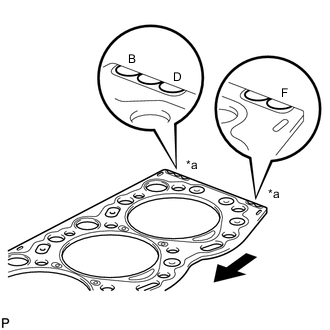
*a Cutout Mark Front Select a new cylinder head gasket.
Tech Tips
New cylinder head gaskets are available in 3 sizes, and are marked using cutouts for size B, D or F.
New Cylinder Head Gasket Thickness Mark Specified Condition B 1.40 to 1.50 mm (0.0552 to 0.0590 in.) D 1.50 to 1.60 mm (0.0591 to 0.0629 in.) F 1.60 to 1.70 mm (0.0630 to 0.0669 in.)
-
Select the largest piston protrusion value from the measurements made. Then select a new appropriate cylinder head gasket according to the table below.
Gasket Size Item Specified Condition Piston protrusion 0.73 to 0.78 mm (0.0288 to 0.0307 in.) 0.83 to 0.88 mm (0.0327 to 0.0346 in.) 0.93 to 0.98 mm (0.0367 to 0.0385 in.) Gasket to be used B D F
-
-
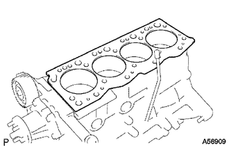
Place a new cylinder head gasket in position on the cylinder block sub-assembly.
Note
Make sure the cylinder head gasket is installed facing the proper direction.
-
-
INSTALL CYLINDER HEAD SUB-ASSEMBLY
*a Timing Mark Turn Tech Tips
-
The cylinder head set bolts are tightened in 3 progressive steps.
-
Set the No. 1 cylinder to 90° BTDC/compression to avoid interference with the piston top and valve head.
-
If any cylinder head set bolt is broken or deformed, replace it.
-
Using the crankshaft pulley bolt, turn the crankshaft 90° counterclockwise, and align the timing mark of the crankshaft timing pulley with the protrusion of the timing belt case sub-assembly.
-
Place the cylinder head sub-assembly on the cylinder block sub-assembly.
Note
-
Make sure that no oil is on the mounting surface of the cylinder head sub-assembly.
-
Place the cylinder head sub-assembly on the cylinder block sub-assembly gently in order not to damage the cylinder head gasket with the bottom part of the cylinder head sub-assembly.
-
-
Apply a light coat of engine oil to the threads and under the heads of the cylinder head set bolts.
-
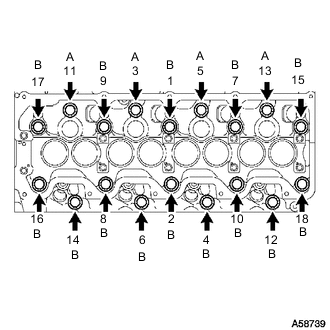
Install and uniformly tighten the 18 cylinder head set bolts, in several passes in the sequence shown in the illustration.
- Torque:
- 78 N*m { 795 kgf*cm, 58 ft.*lbf }
Standard Bolt Length Item Specified Condition Bolt A 107 mm (4.21 in.) Bolt B 127 mm (5.00 in.) If any of the cylinder head set bolts does not meet the torque specification, replace it.
-
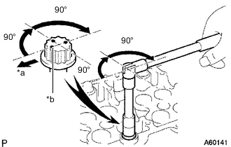
*a Front *b Paint Mark Mark the front of each cylinder head set bolt with paint.
-
Further tighten the cylinder head set bolts by 90° in the sequence shown in the illustration above.
-
Finally, tighten the cylinder head set bolts by an additional 90°.
-
Check that the painted mark are now facing rearward.
-
-
CONNECT FUEL HOSE
-
Connect the fuel hose to the nozzle leakage pipe assembly, and slide the clamp to secure the hose.
-
-
CONNECT WIRE HARNESS
-
Attach the 7 wire harness clamps and connect the wire harness.
-
Connect the engine coolant temperature sensor connector.
-
Connect the engine wire and install the No. 2 glow plug resistor insulator and plate washer with the nut.
- Torque:
- 5.0 N*m { 51 kgf*cm, 44 in.*lbf }
-
-
INSTALL INJECTION PIPE SUB-ASSEMBLY
-
CONNECT HEATER WATER HOSE SUB-ASSEMBLY
-
INSTALL VENTURI ASSEMBLY
-
INSTALL EXHAUST MANIFOLD
-
INSTALL CAMSHAFT
-
BLEED AIR FROM FUEL SYSTEM
-
INSPECT FOR ENGINE OIL LEAK
-
INSPECT FOR COOLANT LEAK
-
INSPECT FOR FUEL LEAK
-
INSPECT FOR EXHAUST GAS LEAK