CYLINDER HEAD GASKET REMOVAL
CAUTION / NOTICE / HINT
The necessary procedures (adjustment, calibration, initialization or registration) that must be performed after parts are removed, installed or replaced during the cylinder head gasket removal/installation are shown below.
| Replacement Part or Procedure | Necessary Procedures | Effects/Inoperative when not Performed | Link |
|---|---|---|---|
| Replacement of timing belt | Mode reset operation |
|
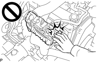
CAUTION:
To prevent burns, do not touch the engine, exhaust manifold or other high temperature components while the engine is hot.
PROCEDURE
-
REMOVE CAMSHAFT
-
REMOVE EXHAUST MANIFOLD
-
REMOVE VENTURI ASSEMBLY
-
DISCONNECT HEATER WATER HOSE SUB-ASSEMBLY
-
REMOVE INJECTION PIPE SUB-ASSEMBLY
-
DISCONNECT WIRE HARNESS
-
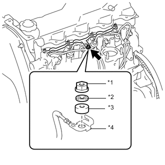
*1 Nut *2 Plate Washer *3 No. 2 Glow Plug Resistor Insulator *4 Wire Harness Remove the nut, plate washer and No. 2 glow plug resistor insulator and disconnect the wire harness.
-
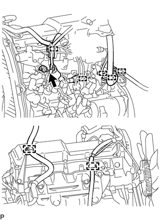
Disconnect the engine coolant temperature sensor connector.
-
Detach the 7 wire harness clamps and disconnect the wire harness.
-
-
DISCONNECT FUEL HOSE
-
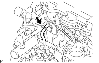
Slide the clamp and disconnect the fuel hose from the nozzle leakage pipe assembly.
-
-
REMOVE CYLINDER HEAD SUB-ASSEMBLY
-
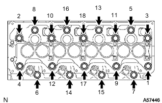
Uniformly loosen and remove the 18 cylinder head set bolts in several steps in the sequence shown.
Note
Cylinder head warpage or cracking could result from removing bolts in the incorrect order.
-
Lift the cylinder head sub-assembly from the dowels on the cylinder block sub-assembly, and place the cylinder head sub-assembly on wooden blocks on a bench.
Note
Be careful not to damage the contact surfaces of the cylinder head sub-assembly and cylinder block sub-assembly.
Tech Tips
If the cylinder head sub-assembly is difficult to lift, use a screwdriver to pry between the cylinder head sub-assembly and cylinder block sub-assembly.
-
-
INSPECT CYLINDER HEAD SET BOLT
-
REMOVE CYLINDER HEAD GASKET