CAUTION / NOTICE / HINT
The necessary procedures (adjustment, calibration, initialization, or registration) that must be performed after parts are removed, installed, or replaced during the fuel pump removal/installation are shown below.
| Replacement Part or Procedure | Necessary Procedures | Effects/Inoperative when not Performed | Link |
|---|---|---|---|
| Replacement of fuel pump | Inspection after repair | Poor idle, engine start, etc. |
PROCEDURE
- Click here
REMOVE FUEL TANK ASSEMBLY
- Click here
REMOVE FUEL TANK CLAMP
-
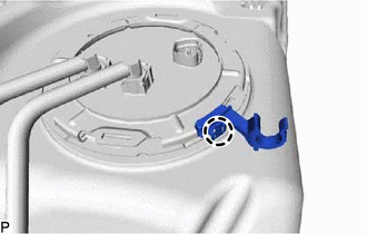
Detach the claw and remove the fuel tank clamp.
-
- Click here
REMOVE FUEL SUCTION WITH PUMP AND GAUGE TUBE ASSEMBLY
-
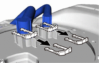
Remove the 2 tube joint clips and pull out the fuel tank main tube sub-assembly and fuel tank return tube from the fuel suction with pump and gauge tube assembly.
Note: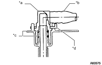
*a Fuel Tube Joint *b Fuel Tube *c O-Ring *d Tube Joint Clip
-
Remove any dirt and foreign matter on the fuel tube joint before performing this work.
-
Do not allow any scratches or foreign matter on the parts when disconnecting them, as the fuel tube joint contains the O-rings that seal the plug.
-
Perform this work by hand. Do not use any tools.
-
Do not forcibly bend or twist the nylon tube.
-
Protect the disconnected parts by covering them with plastic bags and tape after disconnecting the fuel tank main tube sub-assembly and fuel tank return tube.
-
-
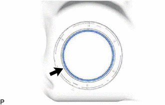
Remove the fuel pump gauge retainer from the fuel tank assembly.
-
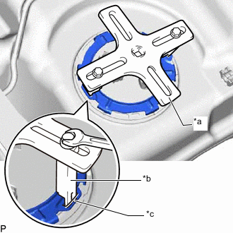
*a SST (Plate) *b SST (Claw) *c Insertion Point Set the 2 claws and plate of SST on the fuel pump gauge retainer.
09808-14030 09808-01030 09808-01040 Tip:Securely insert the ends of SST into the insertion points in the fuel pump gauge retainer.
-
While firmly pressing the claws of SST into the insertion points in the fuel pump gauge, tighten the bolts of the claws.
-

Attach the handle of SST.
09808-14030 09808-01010 -
While lightly pressing down on SST so it does not come off the fuel pump gauge retainer, slowly turn the handle and remove the fuel pump gauge retainer.
Note:
-
Do not use any tools other than SST, such as a screwdriver, etc.
-
Do not use excessive force when pressing down on SST, as the fuel pump gauge retainer will place excessive force on the fuel suction with pump and gauge tube assembly and fuel pump gauge retainer and be difficult to remove, and parts may be damaged.
-
Be sure to keep the handle level when turning it, as SST may slip off the retainer if the handle is turned at an angle with excessive force.
-
Do not use an impact wrench or turn the handle with excessive force, as parts may be damaged.
-
If SST slips off the retainer, loosen the bolts and reattach SST to the retainer.
-
-
-
Remove the fuel suction with pump and gauge tube assembly from the fuel tank assembly.
Note:Be careful not to bend the arm of the fuel sender gauge.
-
Remove the fuel suction tube set gasket from the fuel tank assembly.
-