CAMSHAFT INSTALLATION

CAUTION / NOTICE / HINT
Note
-
When replacing the parts in the following chart (A), replace the No. 1 injection pipe sub-assembly, No. 2 injection pipe sub-assembly, No. 3 injection pipe sub-assembly, No. 4 injection pipe sub-assembly and/or fuel inlet pipe sub-assembly with new ones.
Replaced Parts (A) Pipes Requiring New Replacement
-
Injector assembly (including shuffling the injector assemblies between the cylinders)
-
Common rail assembly
-
Cylinder head sub-assembly
-
No. 1 injection pipe sub-assembly
-
No. 2 injection pipe sub-assembly
-
No. 3 injection pipe sub-assembly
-
No. 4 injection pipe sub-assembly
-
Supply pump assembly
-
Common rail assembly
-
Cylinder block sub-assembly
-
Cylinder head sub-assembly
-
Cylinder head gasket
-
Timing Gear Case Assembly
Fuel inlet pipe sub-assembly -
-
After removing the No. 1 injection pipe sub-assembly, No. 2 injection pipe sub-assembly, No. 3 injection pipe sub-assembly, No. 4 injection pipe sub-assembly and fuel inlet pipe sub-assembly, clean them with a brush and compressed air.
PROCEDURE
-
INSTALL CAMSHAFT SUB-ASSEMBLY
-
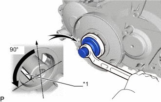
*1 Key Using the crankshaft pulley bolt, set the No. 1 cylinder to 90° BTDC/compression.
Tech Tips
Set the No. 1 cylinder to 90° BTDC/compression to prevent the top of the piston from hitting against the valve head.
-
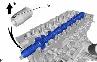
*a Key Groove *b Upward Install the camshaft sub-assembly.
-
Apply engine oil to the thrust portion of the intake camshaft sub-assembly.
-
Place the intake camshaft sub-assembly on the cylinder head sub-assembly with the key groove facing upward.
-
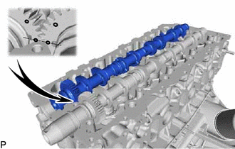
Align the timing marks (1-dot marks) of the camshaft sub-assembly drive and driven main gears and set the exhaust camshaft sub-assembly in place.
-
-
Remove any old seal packing (FIPG material) from the No. 1 camshaft bearing cap.
-
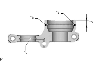
*a Seal Packing *b 8.0 mm (0.315 in.) *c Oil Passage Apply seal packing to the specified areas shown in the illustration.
Seal packing Toyota Genuine Seal Packing Black, Three Bond 1207B or equivalent Standard seal diameter 4 mm (0.157 in.) Note
-
Do not allow seal packing to contact the oil passage of the camshaft bearing cap.
-
After applying seal packing, install the camshaft bearing caps within 3 minutes and tighten the bolts within 15 minutes.
-
Do not start the engine for at least 2 hours after installation.
-
-
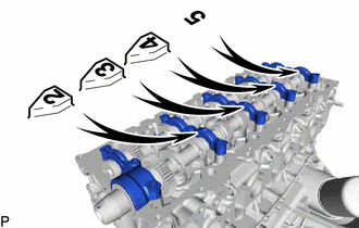
Install the No. 1 camshaft bearing cap, 3 No. 2 camshaft bearing caps and No. 3 camshaft bearing cap to their proper locations from the cylinder head sub-assembly.
-
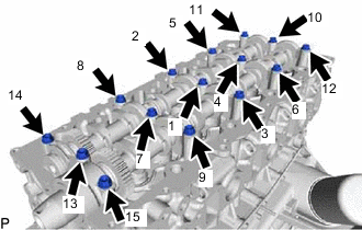
Apply a light coat of engine oil to the threads and under the heads of the camshaft bearing cap bolts.
-
Install and uniformly tighten the 15 camshaft bearing cap bolts in several passes in the sequence shown in the illustration.
- Torque:
- 19 N*m { 194 kgf*cm, 14 ft.*lbf }
-
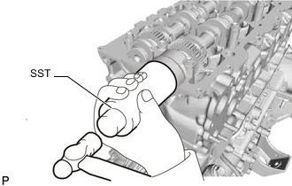
Install a new camshaft oil seal.
-
Apply MP grease to the lip of a new camshaft oil seal.
-
Using SST and a hammer, tap in the camshaft oil seal until its surface is flush with the surfaces of the camshaft bearing cap and cylinder head sub-assembly.
- SST
- 09608-06041
-
-
-
INSTALL NO. 2 TIMING BELT COVER
-
INSTALL CAMSHAFT TIMING PULLEY
-
INSTALL NO. 1 TIMING BELT IDLER SUB-ASSEMBLY
-
INSTALL TIMING BELT
-
INSPECT AND ADJUST VALVE CLEARANCE
-
INSTALL NO. 1 TIMING BELT COVER
-
INSTALL INJECTOR ASSEMBLY
-
INSPECT FOR FUEL LEAK
-
INSTALL CYLINDER HEAD COVER SUB-ASSEMBLY
-
INSTALL NO. 2 NOZZLE LEAKAGE PIPE ASSEMBLY
-
INSTALL NO. 4 INJECTION PIPE SUB-ASSEMBLY
-
INSTALL NO. 1, NO. 2 AND NO. 3 INJECTION PIPE SUB-ASSEMBLY
-
INSTALL ENGINE OIL LEVEL DIPSTICK GUIDE
-
INSTALL MANIFOLD STAY
-
INSTALL NO. 1 INTAKE PIPE
-
INSTALL FAN SHROUD
-
INSTALL NO. 1 RADIATOR HOSE
-
ADD ENGINE OIL
-
BLEED AIR FROM FUEL SYSTEM
-
ADD ENGINE COOLANT
-
INSPECT FOR COOLANT LEAK
-
INSPECT FOR OIL LEAK
-
INSPECT FOR FUEL LEAK
-
INSTALL NO. 1 ENGINE UNDER COVER SUB-ASSEMBLY (for 4WD and Pre-Runner)
-
INSPECT ENGINE OIL LEVEL