CYLINDER BLOCK REPLACEMENT
PROCEDURE
-
REPLACE STRAIGHT PIN
Note
It is not necessary to remove the straight pin unless it is being replaced.
-
Remove the straight pin from the cylinder block sub-assembly.
-
Using a plastic-faced hammer, tap in a new straight pin to the cylinder block sub-assembly.
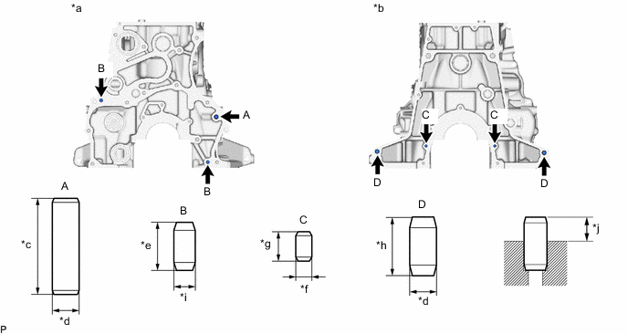
*a Engine Front Side *b Engine Rear Side *c 36 mm (1.42 in.) *d 10 mm (0.394 in.) *e 18 mm (0.709 in.) *f 6.0 mm (0.236 in.) *g 11 mm (0.433 in.) *h 22 mm (0.866 in.) *i 8.0 mm (0.315 in.) *j Protrusion Height Standard Protrusion Height Item Specified Condition Straight Pin A 18 to 20 mm (0.709 to 0.787 in.) Straight Pin B 8.0 to 10 mm (0.315 to 0.394 in.) Straight Pin C 4.0 to 6.0 mm (0.157 to 0.236 in.) Straight Pin D 10 to 12 mm (0.394 to 0.472 in.)
-
-
REPLACE RING PIN
Note
It is not necessary to remove the ring pin unless it is being replaced.
-
Remove the ring pin from the cylinder block sub-assembly.
-
Using a plastic-faced hammer, tap in a new ring pin to the cylinder block sub-assembly.
Standard protrusion height 5.5 to 7.5 mm (0.217 to 0.295 in.) 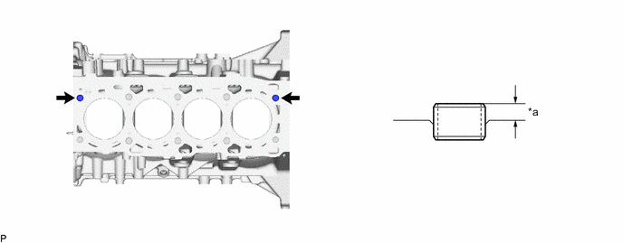
*a Protrusion Height - -
-