PROCEDURE
- Click here
REPLACE INTAKE VALVE GUIDE BUSH
-
Heat the cylinder head sub-assembly to approximately 80 to 100°C (176 to 212°F).
CAUTION:Be sure to wear protective gloves.
-
Place the cylinder head sub-assembly on wooden blocks.
-
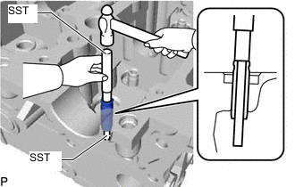
Using SST and a hammer, tap out the intake valve guide bush from the cylinder head sub-assembly.
09201-10000 09201-01060 09950-70010 09951-07100 -
Using a caliper gauge, measure the intake valve guide bush bore diameter of the cylinder head sub-assembly.
If the intake valve guide bush bore diameter of the cylinder head sub-assembly is more than 11.006 mm (0.433 in.), machine the intake valve guide bush bore diameter to between 11.035 and 11.056 mm (0.434 and 0.435 in.).
If the intake valve guide bush bore diameter of the cylinder head sub-assembly is more than 11.056 mm (0.435 in.), replace the cylinder head sub-assembly.
-
Select a new intake valve guide bush (STD or O/S 0.05).
Intake Valve Guide Bush Bush Size Specified Condition Use STD 11.033 to 11.044 mm (0.4344 to 0.4348 in.) Use O/S 0.05 11.083 to 11.094 mm (0.4363 to 0.4368 in.) -
Heat the cylinder head sub-assembly to approximately 80 to 100°C (176 to 212°F).
CAUTION:Be sure to wear protective gloves.
-
Place the cylinder head sub-assembly on wooden blocks.
-
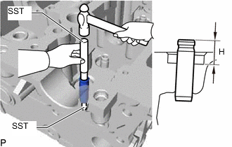
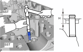
Using SST and a hammer, tap in a new intake valve guide bush to the specified protrusion height.
09201-10000 09201-01060 09950-70010 09951-07100 Standard protrusion height (H) 15.5 to 15.9 mm (0.610 to 0.626 in.) -
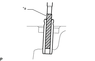
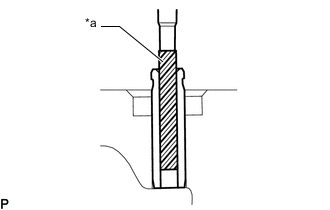
*a Sharp 6.0 mm Reamer Using a sharp 6.0 mm reamer, ream the intake valve guide bush to obtain the standard specified clearance between the intake valve guide bush and intake valve stem.
Standard oil clearance 0.025 to 0.060 mm (0.000984 to 0.00236 in.)
-
- Click here
REPLACE EXHAUST VALVE GUIDE BUSH
-
Heat the cylinder head sub-assembly to approximately 80 to 100°C (176 to 212°F).
CAUTION:Be sure to wear protective gloves.
-
Place the cylinder head sub-assembly on wooden blocks.
-
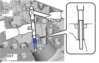
Using SST and a hammer, tap out the exhaust valve guide bush from the cylinder head sub-assembly.
09201-10000 09201-01060 09950-70010 09951-07100 -
Using a caliper gauge, measure the exhaust valve guide bush bore diameter of the cylinder head sub-assembly.
If the exhaust valve guide bush bore diameter of the cylinder head sub-assembly is more than 11.006 mm (0.433 in.), machine the exhaust valve guide bush bore diameter to between 11.035 and 11.056 mm (0.434 and 0.435 in.).
If the exhaust valve guide bush bore diameter of the cylinder head sub-assembly is more than 11.056 mm (0.435 in.), replace the cylinder head sub-assembly.
-
Select a new exhaust valve guide bush (STD or O/S 0.05).
Exhaust Valve Guide Bush Bush Size Specified Condition Use STD 11.033 to 11.044 mm (0.4344 to 0.4348 in.) Use O/S 0.05 11.083 to 11.094 mm (0.4363 to 0.4368 in.) -
Heat the cylinder head sub-assembly to approximately 80 to 100°C (176 to 212°F).
CAUTION:Be sure to wear protective gloves.
-
Place the cylinder head sub-assembly on wooden blocks.
-
Using SST and a hammer, tap in a new exhaust valve guide bush to the specified protrusion height.
09201-10000 09201-01060 09950-70010 09951-07100 Standard protrusion height (H) 15.5 to 15.9 mm (0.610 to 0.626 in.) -
*a Sharp 6.0 mm Reamer Using a sharp 6.0 mm reamer, ream the exhaust valve guide bush to obtain the standard specified clearance between the exhaust valve guide bush and exhaust valve stem.
Standard oil clearance 0.035 to 0.070 mm (0.00138 to 0.00276 in.)
-
- Click here
REPLACE RING PIN
Note:It is not necessary to remove the ring pin unless it is being replaced.
-
Remove the ring pin from the cylinder head sub-assembly.
-
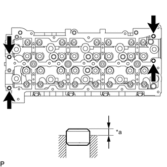
*a Protrusion Height Using a plastic-faced hammer, tap in new ring pins to the cylinder head sub-assembly.
Standard protrusion height 3.5 to 4.5 mm (0.138 to 0.177 in.)
-
- Click here
REPLACE STRAIGHT PIN
Note:It is not necessary to remove the straight pin unless it is being replaced.
-
Remove the straight pin from the cylinder head sub-assembly.
-
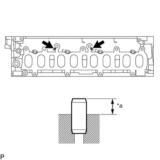
*a Protrusion Height Using a plastic-faced hammer, tap in new straight pins to the cylinder head sub-assembly.
Standard protrusion height 2.0 to 4.0 mm (0.0787 to 0.157 in.)
-