CAUTION / NOTICE / HINT
-
When replacing the parts in the following chart (A), replace the No. 1 injection pipe sub-assembly, No. 2 injection pipe sub-assembly and/or fuel inlet pipe sub-assembly with new ones.
Replaced Parts (A) Pipes Requiring New Replacement Injector assembly (including shuffling the injector assemblies between the cylinders)
-
No. 1 injection pipe sub-assembly
-
No. 2 injection pipe sub-assembly
Supply pump assembly Fuel inlet pipe sub-assembly
-
Common rail assembly
-
Cylinder block sub-assembly
-
Cylinder head sub-assembly
-
Cylinder head gasket
-
Timing chain case assembly
-
No. 1 injection pipe sub-assembly
-
No. 2 injection pipe sub-assembly
-
Fuel inlet pipe sub-assembly
-
-
After removing the No. 1 injection pipe sub-assembly, No. 2 injection pipe sub-assembly and/or fuel inlet pipe sub-assembly, clean them with a brush and compressed air.
-
The injector assembly is a precision instrument. Do not use the injector assembly if it is struck or dropped.
-
The supply pump assembly is a precision instrument. Do not use the supply pump assembly if it is struck or dropped.
-
The common rail assembly is a precision instrument. Do not use the common rail assembly if it is struck or dropped.
-
Hold the supply pump assembly itself during removal and installation. Do not hold the pre-stroke control valve or fuel pipe, etc.
-
Hold the common rail assembly itself during removal and installation. Do not hold the pressure discharge valve or fuel pressure sensor, etc.
-
Make sure foreign matter does not enter the fuel path.
PROCEDURE
- Click here
INSTALL NO. 1 WATER HOSE CLAMP BRACKET (w/ DPF)
-
Install the No. 1 water hose clamp bracket with the bolt to the timing chain case assembly.
10 N*m 102 kgf*cm 7 ft.*lbf
-
- Click here
INSTALL CRANKSHAFT PULLEY
- Click here
INSTALL CRANKSHAFT PULLEY COVER
- Click here
INSTALL VISCOUS HEATER CRANKSHAFT PULLEY (w/ Viscous Heater)
- Click here
INSTALL CAMSHAFT OIL SEAL RETAINER
Note:If the camshaft oil seal retainer is dropped, replace it with a new one.
-
Before installing a new camshaft oil seal retainer, clean the installation surface of the No. 3 camshaft bearing cap and cylinder head sub-assembly and remove any foreign matter.
-
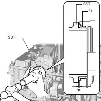
*1 Camshaft Oil Seal Retainer *a Depth Using SST and a hammer, tap in a new camshaft oil seal retainer to the No. 3 camshaft bearing cap and cylinder head sub-assembly as shown in the illustration.
09223-46011 Standard depth 0 to 0.8 mm (0 to 0.0315 in.)
-
- Click here
INSTALL VACUUM PUMP ASSEMBLY
-
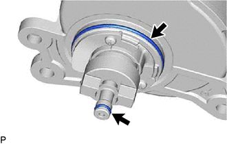
Coat 2 new O-rings with engine oil, and install them to the vacuum pump assembly.
-
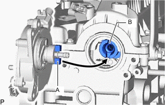
Install the vacuum pump assembly so that the coupling teeth of the vacuum pump assembly labeled A and the groove of the No. 2 camshaft labeled B can engage.
-
Install the vacuum pump assembly with the 3 bolts to the cylinder head sub-assembly.
21 N*m 214 kgf*cm 15 ft.*lbf
-
- Click here
INSTALL NO. 1 VACUUM TRANSMITTING PIPE SUB-ASSEMBLY
-
Install the No. 1 vacuum transmitting pipe sub-assembly with the 3 bolts to the cylinder head sub-assembly.
10 N*m 102 kgf*cm 7 ft.*lbf -
w/ EGR Cooler:
Connect the No. 1 vacuum transmitting hose to the vacuum pump assembly.
-
- Click here
INSTALL V-RIBBED BELT TENSIONER ASSEMBLY
- Click here
INSTALL NO. 1 IDLER PULLEY SUB-ASSEMBLY
- Click here
INSTALL THERMOSTAT
- Click here
INSTALL WATER INLET
-
Install the water inlet with the 3 bolts to the timing chain cover sub-assembly.
13 N*m 133 kgf*cm 10 ft.*lbf
-
- Click here
INSTALL WATER OUTLET SUB-ASSEMBLY
-
Install a new gasket and the water outlet sub-assembly with the 4 bolts and 2 nuts to the timing chain cover sub-assembly.
10 N*m 102 kgf*cm 7 ft.*lbf
-
- Click here
INSTALL NO. 2 WATER BY-PASS PIPE SUB-ASSEMBLY
-
Install the No. 2 water by-pass pipe sub-assembly with the 2 bolts to the engine water pump assembly and water inlet.
10 N*m 102 kgf*cm 7 ft.*lbf -
Connect the No. 3 water by-pass hose to the water outlet sub-assembly, and slide the clamp to secure the hose.
-
- Click here
INSTALL ENGINE OIL PRESSURE SWITCH ASSEMBLY
- Click here
TEMPORARILY INSTALL TURBO OIL INLET PIPE SUB-ASSEMBLY
- Click here
TEMPORARILY INSTALL EXHAUST MANIFOLD WITH TURBOCHARGER SUB-ASSEMBLY
- Click here
INSTALL TURBO OIL OUTLET PIPE
- Click here
TEMPORARILY INSTALL TURBOCHARGER STAY
- Click here
TIGHTEN EXHAUST MANIFOLD WITH TURBOCHARGER SUB-ASSEMBLY
- Click here
TIGHTEN TURBOCHARGER STAY
- Click here
INSTALL NO. 1 VISCOUS HEATER BRACKET SUB-ASSEMBLY (w/ Viscous Heater)
-
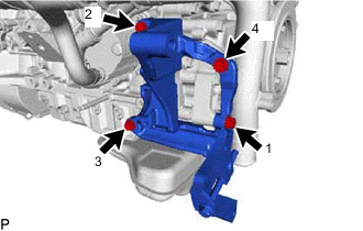
Temporarily install the No. 1 viscous heater bracket sub-assembly with the 4 bolts to the cylinder block sub-assembly and timing chain cover sub-assembly.
-
Tighten the 4 bolts in the sequence shown in the illustration to install the No. 1 viscous heater bracket sub-assembly.
24.5 N*m 250 kgf*cm 18 ft.*lbf
-
- Click here
CONNECT NO. 1 AND NO. 2 TURBO WATER HOSE
- Click here
INSTALL NO. 1 WATER BY-PASS PIPE
-
Install a new gasket and the No. 1 water by-pass pipe with the 3 bolts to the timing chain cover sub-assembly.
10 N*m 102 kgf*cm 7 ft.*lbf Tip:Make sure that the claw of the gasket faces the No. 1 water by-pass pipe.
-
- Click here
INSTALL NO. 3 WATER BY-PASS PIPE
- Click here
INSTALL PCV HOSE (except Cold Area Specification Vehicles)
- Click here
INSTALL TURBINE OUTLET ELBOW (w/o EGR Cooler)
-
Set a new gasket and the turbine outlet elbow to the turbocharger sub-assembly.
-
Temporarily install the exhaust pipe support stay to the cylinder block sub-assembly and turbine outlet elbow with the 3 bolts.
-
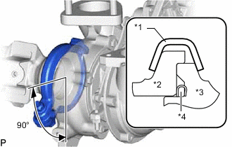
*1 Exhaust Pipe Clamp *2 Turbine Outlet Elbow *3 Turbocharger Sub-assembly *4 Gasket Install a new exhaust pipe clamp to the turbine outlet elbow with a new nut.
18 N*m 184 kgf*cm 13 ft.*lbf -
Tighten the 3 bolts and install the exhaust pipe support stay to the cylinder block sub-assembly and turbine outlet elbow.
38 N*m 387 kgf*cm 28 ft.*lbf
-
- Click here
INSTALL EXHAUST MANIFOLD CONVERTER SUB-ASSEMBLY (w/ EGR Cooler)
-
w/ DPF:
-
w/o DPF:
-
- Click here
INSTALL NO. 2 EXHAUST PIPE SUPPORT STAY (w/o EGR Cooler)
-
Install the No. 2 exhaust pipe support stay to the cylinder block sub-assembly and turbine outlet elbow with 2 new nuts and the bolt.
38 N*m 387 kgf*cm 28 ft.*lbf
-
- Click here
INSTALL NO. 2 EXHAUST PIPE SUPPORT STAY (w/ EGR Cooler)
-
w/ DPF:
-
w/o DPF:
-
- Click here
INSTALL NO. 1 TURBO INSULATOR (w/o EGR Cooler)
-
Install the No. 1 turbo insulator to the exhaust manifold and turbocharger sub-assembly with the 3 bolts.
12 N*m 122 kgf*cm 9 ft.*lbf
-
- Click here
INSTALL NO. 1 TURBO INSULATOR (w/ EGR Cooler)
-
w/ DPF:
-
w/o DPF:
-
- Click here
INSTALL NO. 1 EXHAUST MANIFOLD HEAT INSULATOR (w/o EGR Cooler)
-
Install the No. 1 exhaust manifold heat insulator to the exhaust manifold with the 3 bolts.
12 N*m 122 kgf*cm 9 ft.*lbf
-
- Click here
INSTALL NO. 1 EXHAUST MANIFOLD HEAT INSULATOR (w/ EGR Cooler)
-
w/ DPF:
-
w/o DPF:
-
- Click here
INSTALL AIR FUEL RATIO SENSOR (w/ DPF)
- Click here
INSTALL NO. 1 INJECTOR HOLDER (w/ DPF)
- Click here
CONNECT NO. 4 WATER BY-PASS HOSE (w/ DPF)
-
Connect the No. 4 water by-pass hose to the No. 1 injector holder, and slide the clamp to secure the hose.
-
- Click here
INSTALL NO. 5 WATER BY-PASS HOSE (w/ DPF)
-
Attach the clamp and install the No. 5 water by-pass hose to the No. 1 water hose clamp bracket.
-
Connect the No. 5 water by-pass hose to the No. 1 injector holder and water outlet sub-assembly, and slide the 2 clamps to secure the hose.
-
- Click here
INSTALL PCV PIPE (for Cold Area Specification Vehicles)
- Click here
INSTALL ENGINE COOLANT TEMPERATURE SENSOR
- Click here
INSTALL IDLER PULLEY ASSEMBLY (w/o Air Conditioning System)
Note:Install the idler pulley assembly exactly as described in the procedures below to properly secure and prevent damage to the fan and generator V belt.
-
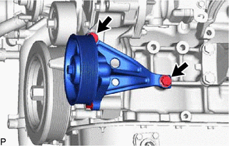
Temporarily install the idler pulley assembly with the 2 bolts to the cylinder block sub-assembly.
Tip:Temporarily install the idler pulley assembly with the 2 bolts so that the idler pulley assembly can be moved by hand.
-
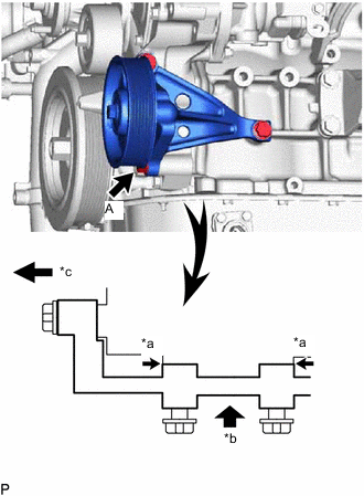
*a No Clearance *b Push *c Front Push the idler pulley assembly toward the cylinder block sub-assembly as shown in the illustration and tighten bolt A.
39 N*m 398 kgf*cm 29 ft.*lbf Tip:Make sure there is no clearance between the cylinder block sub-assembly and idler pulley assembly as shown in the illustration.
-
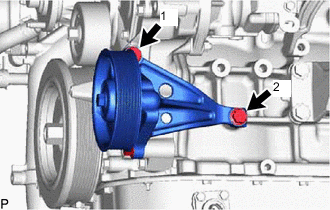
Uniformly tighten the 2 bolts in the order shown in the illustration.
39 N*m 398 kgf*cm 29 ft.*lbf
-
- Click here
INSTALL NO. 1 COMPRESSOR MOUNTING BRACKET (w/ Air Conditioning System)
Note:Install the No. 1 compressor mounting bracket exactly as described in the procedures below to properly secure and prevent damage to the fan and generator V belt.
-
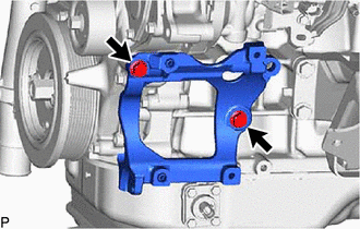
Temporarily install the No. 1 compressor mounting bracket with the 2 bolts to the cylinder block sub-assembly.
Tip:Temporarily install the No. 1 compressor mounting bracket with the 2 bolts so that the No. 1 compressor mounting bracket can be moved by hand.
-
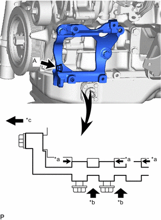
*a No Clearance *b Push *c Front Push the No. 1 compressor mounting bracket toward the cylinder block sub-assembly as shown in the illustration and tighten bolt A.
39 N*m 398 kgf*cm 29 ft.*lbf Tip:Make sure there is no clearance between the cylinder block sub-assembly and No. 1 compressor mounting bracket as shown in the illustration.
-

Uniformly tighten the 3 bolts in the order shown in the illustration.
39 N*m 398 kgf*cm 29 ft.*lbf
-
- Click here
INSTALL NO. 5 WATER BY-PASS PIPE SUB-ASSEMBLY
-
Install a new gasket and the No. 5 water by-pass pipe sub-assembly with the 3 bolts to the cylinder block sub-assembly.
25 N*m 255 kgf*cm 18 ft.*lbf Tip:Make sure that the claw of the gasket faces the No. 5 water by-pass pipe sub-assembly.
-
- Click here
INSTALL NO. 3 NOZZLE LEAKAGE PIPE (w/o Pressurized Fuel Filter)
-
Install the No. 3 nozzle leakage pipe with the 2 nuts to the cylinder block sub-assembly.
21 N*m 214 kgf*cm 15 ft.*lbf
-
- Click here
INSTALL DIESEL FUEL FILTER ASSEMBLY (w/ Pressurized Fuel Filter)
-
Install the diesel fuel filter assembly with the 2 nuts to the cylinder block sub-assembly.
21 N*m 214 kgf*cm 15 ft.*lbf
-
- Click here
INSTALL HOSE BRACKET
-
Install the hose bracket with the 2 bolts to the cylinder head sub-assembly.
10 N*m 102 kgf*cm 7 ft.*lbf
-
- Click here
INSTALL GLOW PLUG ASSEMBLY
- Click here
INSTALL NO. 1 GLOW PLUG CONNECTOR
- Click here
INSTALL COMMON RAIL ASSEMBLY
- Click here
TEMPORARILY INSTALL NO. 1 AND NO. 2 INJECTION PIPE SUB-ASSEMBLY
- Click here
TIGHTEN INJECTOR ASSEMBLY
- Click here
TIGHTEN NO. 1 AND NO. 2 INJECTION PIPE SUB-ASSEMBLY
- Click here
INSTALL WIRING HARNESS CLAMP BRACKET
-
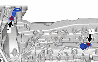
Install the 2 wiring harness clamp brackets with the 2 bolts to the cylinder head cover sub-assembly.
for bolt A 10 N*m 102 kgf*cm 7 ft.*lbf for bolt B 8.4 N*m 86 kgf*cm 74 in.*lbf
-
- Click here
INSTALL NOZZLE LEAKAGE PIPE ASSEMBLY
- Click here
INSTALL NO. 1 FUEL PIPE (w/ DPF)
- Click here
INSTALL WIRING HARNESS CLAMP BRACKET
- Click here
INSTALL INTAKE MANIFOLD
- Click here
INSTALL NO. 2 NOZZLE LEAKAGE PIPE ASSEMBLY
- Click here
INSTALL FUEL INLET PIPE SUB-ASSEMBLY
- Click here
INSTALL NO. 3 FUEL PIPE (w/ Pressurized Fuel Filter)
- Click here
INSTALL NO. 4 FUEL PIPE SUB-ASSEMBLY (w/ Pressurized Fuel Filter)
- Click here
INSTALL NO. 1 FUEL HOSE
- Click here
INSTALL NO. 2 FUEL HOSE
- Click here
INSTALL FUEL PUMP MOTOR WIRE
- Click here
INSTALL FUEL INJECTION PUMP COVER SUB-ASSEMBLY
- Click here
INSTALL MANIFOLD STAY
- Click here
INSTALL WIRING HARNESS CLAMP BRACKET
- Click here
INSTALL NO. 2 FUEL PIPE
-
Install the No. 2 fuel pipe with the bolt to the manifold stay.
10 N*m 102 kgf*cm 7 ft.*lbf -
Connect the No. 1 fuel hose to the No. 2 fuel pipe, and slide the clamp to secure the hose.
-
- Click here
INSTALL ENGINE OIL LEVEL DIPSTICK GUIDE
- Click here
INSTALL EGR HOLE COVER PLATE (w/o EGR System)
-
Using an E8 "TORX" socket wrench, install 2 new stud bolts to the exhaust manifold.
10 N*m 102 kgf*cm 7 ft.*lbf -
Install 2 new gaskets and the 2 EGR cooler hole plates to the intake manifold and exhaust manifold with 4 new nuts.
29 N*m 296 kgf*cm 21 ft.*lbf
-
- Click here
INSTALL EGR VALVE ADAPTER SUB-ASSEMBLY (w/o EGR System)
-
Temporarily install the EGR valve adapter sub-assembly to the intake manifold with the 4 bolts.
-
Tighten the 4 bolts in the order shown in the illustration.
Note:Make sure to tighten the bolts in the order.
21 N*m 214 kgf*cm 15 ft.*lbf
-
- Click here
INSTALL EGR VALVE ADAPTER SUB-ASSEMBLY WITH ELECTRIC EGR CONTROL VALVE ASSEMBLY (w/ EGR System without EGR Cooler)
-
Temporarily install the EGR valve adapter sub-assembly with electric EGR control valve assembly to the intake manifold with the 4 bolts.
-
Tighten the 4 bolts in the order shown in the illustration.
Note:Make sure to tighten the bolts in the order.
21 N*m 214 kgf*cm 15 ft.*lbf
-
- Click here
INSTALL NO. 1 EGR COOLER AND NO. 2 EGR VALVE ASSEMBLY WITH ELECTRIC EGR CONTROL VALVE ASSEMBLY (w/ EGR System with EGR Cooler)
- Click here
INSTALL EGR PIPE WITH COOLER SUB-ASSEMBLY (w/ DPF)
-
Using an E8 "TORX" socket wrench, install 2 new stud bolts to the exhaust manifold.
10 N*m 102 kgf*cm 7 ft.*lbf -
Install 2 new gaskets and the EGR pipe with cooler sub-assembly with the bolt and 4 new nut to the exhaust manifold, electric EGR control valve assembly and No. 1 vacuum transmitting pipe sub-assembly.
for bolt 10 N*m 102 kgf*cm 7 ft.*lbf for nut 29 N*m 296 kgf*cm 21 ft.*lbf
-
- Click here
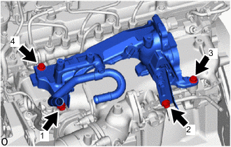
INSTALL NO. 4 WATER BY-PASS PIPE SUB-ASSEMBLY
-
w/ DPF:
-
Install the No. 4 water by-pass pipe sub-assembly with the 2 bolts to the intake manifold.
10 N*m 102 kgf*cm 7 ft.*lbf -
for Cold Area Specification Vehicles:
Attach the clamp and connect the No. 11 water by-pass hose to the No. 2 fuel pipe.
-
Connect the No. 17 water by-pass hose to the EGR pipe with cooler sub-assembly, and slide the clamp to secure the hose.
-
Connect the water hose to the No. 2 EGR valve assembly, and slide the clamp to secure the hose.
-
Connect the No. 7 water by-pass hose to the No. 4 water by-pass pipe sub-assembly, and slide the clamp to secure the hose.
-
Connect the No. 6 water by-pass hose to the No. 4 water by-pass pipe sub-assembly, and slide the clamp to secure the hose.
-
-
w/o DPF:
-
Install the No. 4 water by-pass pipe sub-assembly with the 2 bolts to the intake manifold.
10 N*m 102 kgf*cm 7 ft.*lbf -
for Cold Area Specification Vehicles:
Attach the clamp and connect the No. 11 water by-pass hose to the No. 2 fuel pipe.
-
Connect the water hose to the No. 2 EGR valve assembly, and slide the clamp to secure the hose.
-
Connect the No. 7 water by-pass hose to the No. 4 water by-pass pipe sub-assembly, and slide the clamp to secure the hose.
-
Connect the No. 6 water by-pass hose to the No. 4 water by-pass pipe sub-assembly, and slide the clamp to secure the hose.
-
-
- Click here
INSTALL VACUUM CONTROL VALVE SET (w/ EGR Cooler)
- Click here
INSTALL NO. 1 EGR PIPE SUB-ASSEMBLY (w/ EGR System)
-
Using an E8 "TORX" socket wrench, install 2 new stud bolts to the exhaust manifold.
10 N*m 102 kgf*cm 7 ft.*lbf -
Install 2 new gaskets and the No. 1 EGR pipe sub-assembly with the bolt and 4 new nut to the exhaust manifold, electric EGR control valve assembly and No. 1 vacuum transmitting pipe sub-assembly.
for bolt 10 N*m 102 kgf*cm 7 ft.*lbf for nut 29 N*m 296 kgf*cm 21 ft.*lbf
-
- Click here
INSTALL CONNECTING WIRE
-
Attach the 2 clamps and install the connecting wire to the hose bracket.
-
Connect the connector to the common rail assembly.
-
- Click here
INSTALL NO. 3 WATER BY-PASS PIPE SUB-ASSEMBLY (w/o EGR Cooler)
-
Install the No. 3 water by-pass pipe sub-assembly to the EGR valve adapter sub-assembly with the 2 bolts.
10 N*m 102 kgf*cm 7 ft.*lbf -
w/ EGR System:
Connect the No. 8 water by-pass hose to the No. 3 water by-pass pipe sub-assembly, and slide the clamp to secure the hose.
-
Connect the No. 4 fuel hose to the No. 3 water by-pass pipe sub-assembly.
-
- Click here
INSTALL NO. 3 WATER BY-PASS PIPE SUB-ASSEMBLY (w/ EGR Cooler)
- Click here
INSTALL NO. 2 EGR PIPE
- Click here
INSTALL EGR VALVE BRACKET
- Click here
INSTALL DIESEL TURBO PRESSURE SENSOR
- Click here
INSTALL GAS FILTER
- Click here
INSTALL ENGINE COVER BRACKET
-
Install the engine cover bracket with the 2 bolts to the cylinder head cover sub-assembly and hose bracket.
21 N*m 214 kgf*cm 15 ft.*lbf
-
- Click here
INSTALL PIPE CLAMP (w/ DPF)
- Click here
TEMPORARILY INSTALL NO. 2 VACUUM PIPE (w/ DPF)
- Click here
TEMPORARILY INSTALL NO. 1 VACUUM PIPE (w/ DPF)
- Click here
TIGHTEN NO. 2 VACUUM PIPE (w/ DPF)
- Click here
TIGHTEN NO. 1 VACUUM PIPE (w/ DPF)
- Click here
INSTALL EXHAUST GAS TEMPERATURE SENSOR (w/ DPF)
- Click here
INSTALL DIFFERENTIAL PRESSURE SENSOR (w/ DPF)
- Click here
INSTALL WATER BY-PASS PLUG (w/o Heater)
-
Install the water by-pass plug to the water outlet sub-assembly, and slide the clamp to secure the plug.
-
- Click here
INSTALL NO. 2 WATER BY-PASS PIPE
- Click here
INSTALL DIESEL THROTTLE BODY ASSEMBLY
- Click here
INSTALL INTERCOOLER AIR TUBE
- Click here
INSTALL ENGINE WIRE
- Click here
INSTALL NO. 2 ENGINE COVER BRACKET
- Click here
INSTALL NO. 2 HOSE TO HOSE TUBE
-
Install the No. 2 hose to hose tube to the cylinder head cover sub-assembly and hose bracket with the 2 bolts.
10 N*m 102 kgf*cm 7 ft.*lbf -
Connect the union to check valve hose to the vacuum pump assembly, and slide the clamp to secure the hose.
-