ENGINE UNIT REMOVAL

CAUTION / NOTICE / HINT
Note
-
When replacing the parts in the following chart (A), replace the No. 1 injection pipe sub-assembly, No. 2 injection pipe sub-assembly and/or fuel inlet pipe sub-assembly with new ones.
Replaced Parts (A) Pipes Requiring New Replacement Injector assembly (including shuffling the injector assemblies between the cylinders)
-
No. 1 injection pipe sub-assembly
-
No. 2 injection pipe sub-assembly
Supply pump assembly Fuel inlet pipe sub-assembly
-
Common rail assembly
-
Cylinder block sub-assembly
-
Cylinder head sub-assembly
-
Cylinder head gasket
-
Timing chain case assembly
-
No. 1 injection pipe sub-assembly
-
No. 2 injection pipe sub-assembly
-
Fuel inlet pipe sub-assembly
-
-
After removing the No. 1 injection pipe sub-assembly, No. 2 injection pipe sub-assembly and/or fuel inlet pipe sub-assembly, clean them with a brush and compressed air.
-
The injector assembly is a precision instrument. Do not use the injector assembly if it is struck or dropped.
-
The supply pump assembly is a precision instrument. Do not use the supply pump assembly if it is struck or dropped.
-
The common rail assembly is a precision instrument. Do not use the common rail assembly if it is struck or dropped.
-
Hold the supply pump assembly itself during removal and installation. Do not hold the pre-stroke control valve or fuel pipe, etc.
-
Hold the common rail assembly itself during removal and installation. Do not hold the pressure discharge valve or fuel pressure sensor, etc.
-
Make sure foreign matter does not enter the fuel path.
PROCEDURE
-
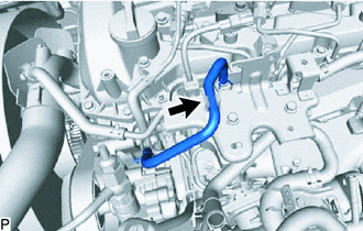
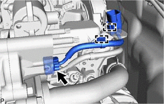
REMOVE NO. 2 HOSE TO HOSE TUBE
-
Slide the clamp and disconnect the union to check valve hose from the vacuum pump assembly.
-
Remove the 2 bolts and No. 2 hose to hose tube from the cylinder head cover sub-assembly and hose bracket.
-
-
REMOVE NO. 2 ENGINE COVER BRACKET
-
REMOVE ENGINE WIRE
-
REMOVE INTERCOOLER AIR TUBE
-
REMOVE DIESEL THROTTLE BODY ASSEMBLY
-
REMOVE NO. 2 WATER BY-PASS PIPE
-
REMOVE WATER BY-PASS PLUG (w/o Heater)
-
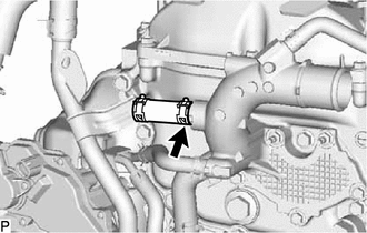
Slide the clamp and remove the water by-pass plug from the water outlet sub-assembly.
-
-
REMOVE DIFFERENTIAL PRESSURE SENSOR (w/ DPF)
-
REMOVE EXHAUST GAS TEMPERATURE SENSOR (w/ DPF)
-
REMOVE NO. 1 VACUUM PIPE (w/ DPF)
-
REMOVE NO. 2 VACUUM PIPE (w/ DPF)
-
REMOVE PIPE CLAMP (w/ DPF)
-
REMOVE ENGINE COVER BRACKET
-
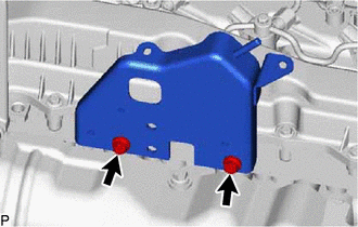
Remove the 2 bolts and engine cover bracket from the cylinder head sub-assembly.
-
-
REMOVE GAS FILTER
-
REMOVE DIESEL TURBO PRESSURE SENSOR
-
REMOVE EGR VALVE BRACKET
-
REMOVE NO. 2 EGR PIPE
-
REMOVE NO. 3 WATER BY-PASS PIPE SUB-ASSEMBLY (w/ EGR Cooler)
-
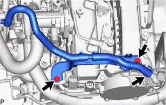
REMOVE NO. 3 WATER BY-PASS PIPE SUB-ASSEMBLY (w/o EGR Cooler)
CAUTION:
To prevent burns, do not touch the engine, exhaust manifold or other high temperature components while the engine is hot.
-
Disconnect the No. 4 fuel hose from the No. 3 water by-pass pipe sub-assembly.
-
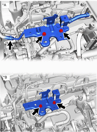
*A w/ EGR System *B w/o EGR System w/ EGR System:
Slide the clamp and disconnect the No. 8 water by-pass hose from the No. 3 water by-pass pipe sub-assembly.
-
Remove the 2 bolts and No. 3 water by-pass pipe sub-assembly from the EGR valve adapter sub-assembly.
-
-
REMOVE CONNECTING WIRE
-
Disconnect the connector from the common rail assembly.
-
Detach the 2 clamps and remove the connecting wire from the hose bracket.
-
-
REMOVE NO. 1 EGR PIPE SUB-ASSEMBLY (w/ EGR System)
-
Remove the 4 nuts, bolt and No. 1 EGR pipe from the exhaust manifold, electric EGR control valve assembly and No. 1 vacuum transmitting pipe sub-assembly.
-
Remove the 2 gaskets from the exhaust manifold and electric EGR control valve assembly.
-
Using an E8 "TORX" socket wrench, remove the 2 stud bolts from the exhaust manifold.
-
-
REMOVE VACUUM CONTROL VALVE SET (w/ EGR Cooler)
-
REMOVE NO. 4 WATER BY-PASS PIPE SUB-ASSEMBLY
-
w/ DPF:
-
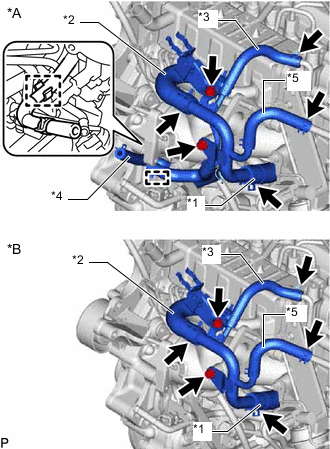
*A for Cold Area Specification Vehicles *B except Cold Area Specification Vehicles *1 No. 6 Water By-pass Hose *2 No. 7 Water By-pass Hose *3 Water Hose *4 No. 11 Water By-pass Hose *5 No. 17 Water By-pass Hose Slide the clamp and disconnect the No. 6 water by-pass hose from the No. 4 water by-pass pipe sub-assembly.
-
Slide the clamp and disconnect the No. 7 water by-pass hose from the No. 4 water by-pass pipe sub-assembly.
-
Slide the clamp and disconnect the water hose from the No. 2 EGR valve assembly.
-
Slide the clamp and disconnect the No. 17 water by-pass hose from the EGR pipe with cooler sub-assembly.
-
for Cold Area Specification Vehicles:
Detach the clamp and disconnect the No. 11 water by-pass hose from the No. 2 fuel pipe.
-
Remove the 2 bolts and No. 4 water by-pass pipe sub-assembly from the intake manifold.
-
-
w/o DPF:
-
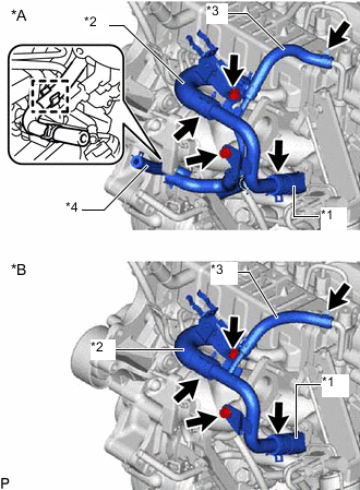
*A for Cold Area Specification Vehicles *B except Cold Area Specification Vehicles *1 No. 6 Water By-pass Hose *2 No. 7 Water By-pass Hose *3 Water Hose *4 No. 11 Water By-pass Hose Slide the clamp and disconnect the No. 6 water by-pass hose from the No. 4 water by-pass pipe sub-assembly.
-
Slide the clamp and disconnect the No. 7 water by-pass hose from the No. 4 water by-pass pipe sub-assembly.
-
Slide the clamp and disconnect the water hose from the No. 2 EGR valve assembly.
-
for Cold Area Specification Vehicles:
Detach the clamp and disconnect the No. 11 water by-pass hose from the No. 2 fuel pipe.
-
Remove the 2 bolts and No. 4 water by-pass pipe sub-assembly from the intake manifold.
-
-
-
REMOVE EGR PIPE WITH COOLER SUB-ASSEMBLY (w/ DPF)
-
Remove the 4 nuts, bolt and EGR pipe with cooler sub-assembly from the exhaust manifold, electric EGR control valve assembly and No. 1 vacuum transmitting pipe sub-assembly.
-
Remove the 2 gaskets from the exhaust manifold and electric EGR control valve assembly.
-
Using an E8 "TORX" socket wrench, remove the 2 stud bolts from the exhaust manifold.
-
-
REMOVE NO. 1 EGR COOLER AND NO. 2 EGR VALVE ASSEMBLY WITH ELECTRIC EGR CONTROL VALVE ASSEMBLY (w/ EGR System with EGR Cooler)
-
REMOVE EGR VALVE ADAPTER SUB-ASSEMBLY WITH ELECTRIC EGR CONTROL VALVE ASSEMBLY (w/ EGR System without EGR Cooler)
-
Remove the 4 bolts and EGR valve adapter sub-assembly with electric EGR control valve assembly from the intake manifold.
-
-
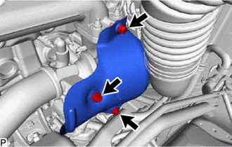
REMOVE EGR VALVE ADAPTER SUB-ASSEMBLY (w/o EGR System)
-
Remove the 4 bolts and EGR valve adapter sub-assembly from the intake manifold.
-
-
REMOVE EGR HOLE COVER PLATE (w/o EGR System)
-
Remove the 4 nuts and 2 EGR cooler hole plates and 2 gaskets from the intake manifold and exhaust manifold.
-
Using an E8 "TORX" socket wrench, remove the 2 stud bolts from the exhaust manifold.
-
-
REMOVE ENGINE OIL LEVEL DIPSTICK GUIDE
-
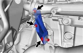
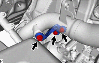
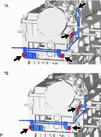
REMOVE NO. 2 FUEL PIPE
-
Slide the clamp and disconnect the No. 1 fuel hose from the No. 2 fuel pipe.
-
Remove the bolt and No. 2 fuel pipe from the manifold stay.
-
-
REMOVE WIRING HARNESS CLAMP BRACKET
-
REMOVE MANIFOLD STAY
-
REMOVE FUEL INJECTION PUMP COVER SUB-ASSEMBLY
-
REMOVE FUEL PUMP MOTOR WIRE
-
REMOVE NO. 2 FUEL HOSE
-
REMOVE NO. 1 FUEL HOSE
-
REMOVE NO. 4 FUEL PIPE SUB-ASSEMBLY (w/ Pressurized Fuel Filter)
-
REMOVE NO. 3 FUEL PIPE (w/ Pressurized Fuel Filter)
-
REMOVE FUEL INLET PIPE SUB-ASSEMBLY
-
REMOVE NO. 2 NOZZLE LEAKAGE PIPE ASSEMBLY
-
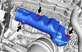
REMOVE INTAKE MANIFOLD
-
REMOVE WIRING HARNESS CLAMP BRACKET
-
REMOVE NO. 1 FUEL PIPE (w/ DPF)
-
REMOVE NOZZLE LEAKAGE PIPE ASSEMBLY
-
REMOVE WIRING HARNESS CLAMP BRACKET
-
Remove the 2 bolts and 2 wiring harness clamp brackets from the cylinder head cover sub-assembly.
-
-
REMOVE NO. 1 AND NO. 2 INJECTION PIPE SUB-ASSEMBLY
-
REMOVE COMMON RAIL ASSEMBLY
-
REMOVE NO. 1 GLOW PLUG CONNECTOR
-
REMOVE GLOW PLUG ASSEMBLY
-
REMOVE HOSE BRACKET
-
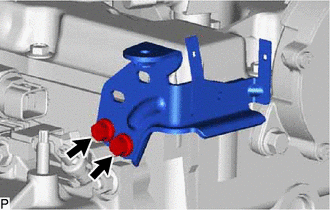
Remove the 2 bolts and hose bracket from the cylinder head sub-assembly.
-
-
REMOVE DIESEL FUEL FILTER ASSEMBLY (w/ Pressurized Fuel Filter)
-
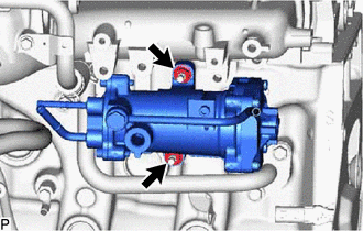
Remove the 2 nuts and diesel fuel filter assembly from the cylinder block sub-assembly.
-
-
REMOVE NO. 3 NOZZLE LEAKAGE PIPE (w/o Pressurized Fuel Filter)
-
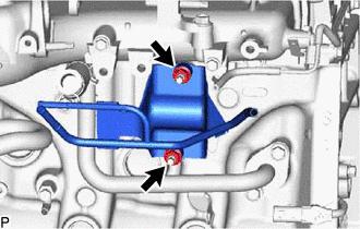
Remove the 2 nuts and No. 3 nozzle leakage pipe from the cylinder block sub-assembly.
-
-
REMOVE NO. 5 WATER BY-PASS PIPE SUB-ASSEMBLY
-
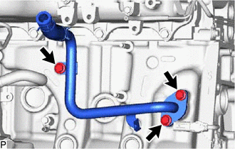
Remove the 3 bolts, No. 5 water by-pass pipe sub-assembly and gasket from the cylinder block sub-assembly.
-
-
REMOVE NO. 1 COMPRESSOR MOUNTING BRACKET (w/ Air Conditioning System)
-
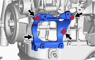
Remove the 4 bolts and No. 1 compressor mounting bracket from the cylinder block sub-assembly, timing chain case assembly and timing chain cover sub-assembly.
-
-
REMOVE IDLER PULLEY ASSEMBLY (w/o Air Conditioning System)
-
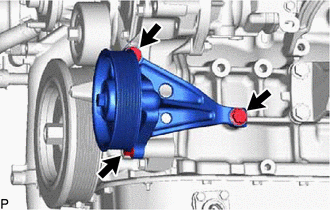
Remove the 3 bolts and idler pulley assembly from the cylinder block sub-assembly, timing chain case assembly and timing chain cover sub-assembly.
-
-
REMOVE ENGINE COOLANT TEMPERATURE SENSOR
-
REMOVE PCV PIPE (for Cold Area Specification Vehicles)
-
REMOVE NO. 5 WATER BY-PASS HOSE (w/ DPF)
-
Slide the 2 clamps and disconnect the No. 5 water by-pass hose from the No. 1 injector holder and water outlet sub-assembly.
-
Detach the clamp and remove the No. 5 water by-pass hose from the No. 1 water hose clamp bracket.
-
-
DISCONNECT NO. 4 WATER BY-PASS HOSE (w/ DPF)
-
Slide the clamp and disconnect the No. 4 water by-pass hose from the No. 1 injector holder.
-
-
REMOVE NO. 1 INJECTOR HOLDER (w/ DPF)
-
REMOVE AIR FUEL RATIO SENSOR (w/ DPF)
-
REMOVE NO. 1 EXHAUST MANIFOLD HEAT INSULATOR (w/ EGR Cooler)
-
w/ DPF:
-
w/o DPF:
-
-
REMOVE NO. 1 EXHAUST MANIFOLD HEAT INSULATOR (w/o EGR Cooler)
-
Remove the 3 bolts and No. 1 exhaust manifold heat insulator from the exhaust manifold.
-
-
REMOVE NO. 1 TURBO INSULATOR (w/ EGR Cooler)
-
w/ DPF:
-
w/o DPF:
-
-
REMOVE NO. 1 TURBO INSULATOR (w/o EGR Cooler)
-
Remove the 3 bolts and No. 1 turbo insulator from the turbine outlet elbow and turbocharger sub-assembly.
-
-
REMOVE NO. 2 EXHAUST PIPE SUPPORT STAY (w/ EGR Cooler)
-
w/ DPF:
-
w/o DPF:
-
-
REMOVE NO. 2 EXHAUST PIPE SUPPORT STAY (w/o EGR Cooler)
-
Remove the bolt, 2 nuts and No. 2 exhaust pipe support stay from the cylinder block sub-assembly and turbine outlet elbow.
-
-
REMOVE EXHAUST PIPE SUPPORT STAY (w/ EGR Cooler)
-
w/ DPF:
-
w/o DPF:
-
-
REMOVE EXHAUST PIPE SUPPORT STAY (w/o EGR Cooler)
-
Remove the 3 bolts and exhaust pipe support stay from the cylinder block sub-assembly and turbine outlet elbow.
-
-
REMOVE EXHAUST MANIFOLD CONVERTER SUB-ASSEMBLY (w/ EGR Cooler)
-
w/ DPF:
-
w/o DPF:
-
-
REMOVE TURBINE OUTLET ELBOW (w/o EGR Cooler)
-
Remove the nut, exhaust pipe clamp and turbine outlet elbow from the turbocharger sub-assembly.
-
Remove the gasket.
-
-
REMOVE PCV HOSE (except Cold Area Specification Vehicles)
-
REMOVE NO. 3 WATER BY-PASS PIPE
-
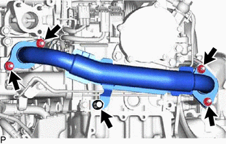
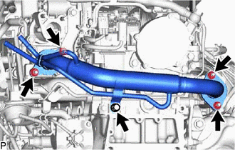
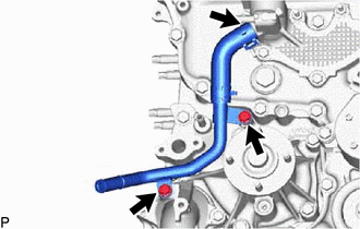
REMOVE NO. 1 WATER BY-PASS PIPE
-
*A for Cold Area Specification Vehicles *B except Cold Area Specification Vehicles Remove the 3 bolts, No. 1 water by-pass pipe and gasket from the timing chain cover sub-assembly.
-
-
DISCONNECT NO. 1 AND NO. 2 TURBO WATER HOSE
-
REMOVE NO. 1 VISCOUS HEATER BRACKET SUB-ASSEMBLY (w/ Viscous Heater)
-
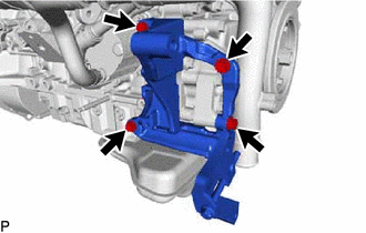
Remove the 4 bolts and No. 1 viscous heater bracket sub-assembly from the cylinder block sub-assembly and timing chain cover sub-assembly.
-
-
REMOVE TURBOCHARGER STAY
-
REMOVE TURBO OIL OUTLET PIPE
-
REMOVE TURBO OIL INLET PIPE SUB-ASSEMBLY
-
REMOVE TURBOCHARGER SUB-ASSEMBLY
-
REMOVE EXHAUST MANIFOLD
-
REMOVE ENGINE OIL PRESSURE SWITCH ASSEMBLY
-
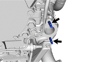
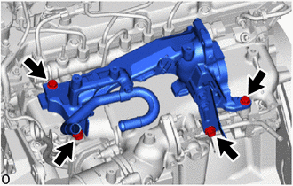
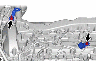
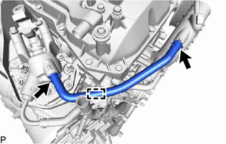
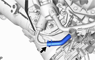
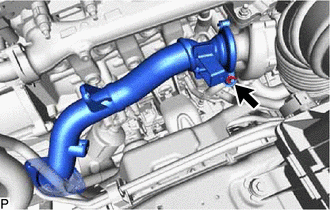
REMOVE NO. 2 WATER BY-PASS PIPE SUB-ASSEMBLY
-
Slide the clamp and disconnect the No. 3 water by-pass hose from the water outlet sub-assembly.
-
Remove the 2 bolts and No. 2 water by-pass pipe sub-assembly from the engine water pump assembly and water inlet.
-
-
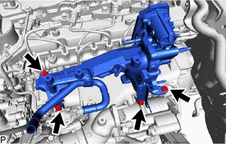
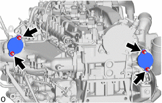
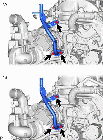
REMOVE WATER OUTLET SUB-ASSEMBLY
-
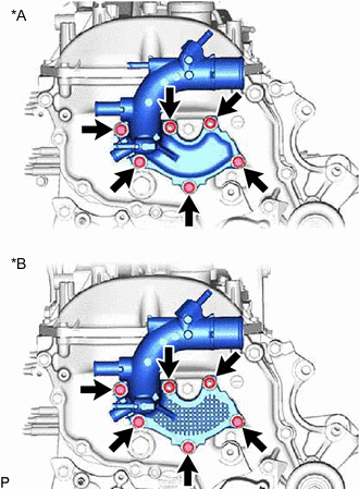
*A w/ DPF *B w/o DPF Remove the 4 bolts, 2 nuts and water outlet sub-assembly from the timing chain cover sub-assembly.
-
Remove the gasket from the timing chain cover sub-assembly.
-
-
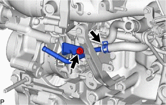
REMOVE WATER INLET
-
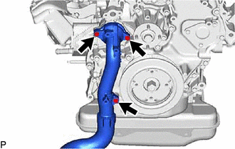
Remove the 3 bolts and water inlet from the timing chain cover sub-assembly.
-
-
REMOVE THERMOSTAT
-
REMOVE NO. 1 IDLER PULLEY SUB-ASSEMBLY
-
REMOVE V-RIBBED BELT TENSIONER ASSEMBLY
-
REMOVE NO. 1 VACUUM TRANSMITTING PIPE SUB-ASSEMBLY
-
*A w/ EGR Cooler *B w/o EGR Cooler w/ EGR Cooler:
Disconnect the No. 1 vacuum transmitting hose from the vacuum pump assembly.
-
Remove the 3 bolts and No. 1 vacuum transmitting pipe sub-assembly from the cylinder head sub-assembly.
-
-
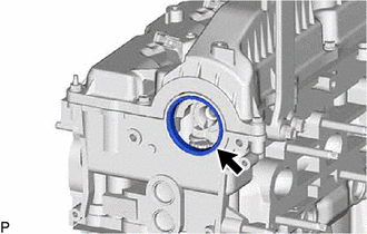
REMOVE VACUUM PUMP ASSEMBLY
-
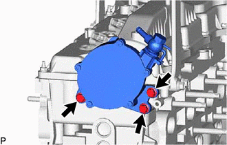
Remove the 3 bolts and vacuum pump assembly from the cylinder head sub-assembly.
-
Remove the 2 O-rings from the vacuum pump assembly.
-
-
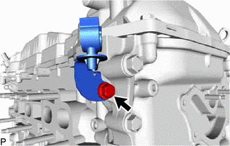
REMOVE CAMSHAFT OIL SEAL RETAINER
-
Remove the camshaft oil seal retainer from the No. 3 camshaft bearing cap and cylinder head sub-assembly.
-
-
REMOVE VISCOUS HEATER CRANKSHAFT PULLEY (w/ Viscous Heater)
-
REMOVE CRANKSHAFT PULLEY COVER
-
REMOVE CRANKSHAFT PULLEY
-
REMOVE NO. 1 WATER HOSE CLAMP BRACKET (w/ DPF)
-
Remove the bolt and No. 1 water hose clamp bracket from the timing chain case assembly.
-