CAMSHAFT(w/o EGR Cooler) REMOVAL
CAUTION / NOTICE / HINT
The necessary procedures (adjustment, calibration, initialization, or registration) that must be performed after parts are removed, installed, or replaced during the camshaft removal/installation are shown below.
| Replacement Part or Procedure | Necessary Procedures | Effects/Inoperative when not Performed | Link |
|---|---|---|---|
| Replacement of injector assembly |
|
Engine starting | |
|
Perform initialization | - |
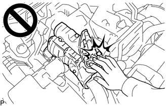
CAUTION:
To prevent burns, do not touch the engine, exhaust manifold or other high temperature components while the engine is hot.
Note
-
When replacing the parts in the following chart (A), replace the No. 1 injection pipe sub-assembly, No. 2 injection pipe sub-assembly and/or fuel inlet pipe sub-assembly with new ones.
Replaced Parts (A) Pipes Requiring New Replacement Injector assembly (including shuffling the injector assemblies between the cylinders)
-
No. 1 injection pipe sub-assembly
-
No. 2 injection pipe sub-assembly
Supply pump assembly Fuel inlet pipe sub-assembly
-
Common rail assembly
-
Cylinder block sub-assembly
-
Cylinder head sub-assembly
-
Cylinder head gasket
-
Timing chain case assembly
-
No. 1 injection pipe sub-assembly
-
No. 2 injection pipe sub-assembly
-
Fuel inlet pipe sub-assembly
-
-
After removing the No. 1 injection pipe sub-assembly, No. 2 injection pipe sub-assembly and/or fuel inlet pipe sub-assembly, clean them with a brush and compressed air.
-
The injector assembly is a precision instrument. Do not use the injector assembly if it is struck or dropped.
-
Make sure foreign matter does not enter the fuel path.
PROCEDURE
-
PRECAUTION
Note
After turning the ignition switch off, waiting time may be required before disconnecting the cable from the battery terminal. Therefore, make sure to read the disconnecting the cable from the battery terminal notice before proceeding with work.
-
DISCONNECT CABLE FROM NEGATIVE BATTERY TERMINAL
Note
When disconnecting the cable, some systems need to be initialized after the cable is reconnected.
-
REMOVE NO. 1 ENGINE UNDER COVER ASSEMBLY (for 4WD)
-
DRAIN ENGINE COOLANT
-
REMOVE FRONT BUMPER
-
REMOVE NO. 1 ENGINE COVER SUB-ASSEMBLY
-
REMOVE NO. 1 RADIATOR AIR GUIDE
-
REMOVE NO. 4 AIR HOSE
-
REMOVE NO. 2 AIR TUBE
-
REMOVE NO. 1 RADIATOR HOSE
-
DISCONNECT VANE PUMP OIL RESERVOIR ASSEMBLY
-
REMOVE NO. 1 OIL RESERVOIR BRACKET
-
REMOVE RADIATOR RESERVE TANK ASSEMBLY
-
DISCONNECT NO. 1 OIL COOLER OUTLET HOSE (for Automatic Transmission)
-
DISCONNECT NO. 1 OIL COOLER INLET HOSE (for Automatic Transmission)
-
REMOVE FAN SHROUD
-
DISCONNECT NO. 2 RADIATOR HOSE
-
REMOVE RADIATOR ASSEMBLY
-
REMOVE INTERCOOLER AIR TUBE
-
REMOVE DIESEL THROTTLE BODY ASSEMBLY
-
REMOVE NO. 2 WATER BY-PASS PIPE
-
REMOVE GAS FILTER
-
REMOVE TURBO PRESSURE SENSOR
-
REMOVE NO. 2 HOSE TO HOSE TUBE
-
REMOVE NO. 2 ENGINE COVER BRACKET
-
DISCONNECT FUEL FILTER ASSEMBLY
-
DISCONNECT ENGINE WIRE
-
REMOVE EGR VALVE BRACKET
-
REMOVE NO. 2 EGR PIPE
-
REMOVE ELECTRIC EGR CONTROL VALVE ASSEMBLY
-
REMOVE EGR VALVE ADAPTER
-
REMOVE WIRING HARNESS CLAMP BRACKET
-
REMOVE HARNESS BRACKET
-
REMOVE NOZZLE LEAKAGE PIPE ASSEMBLY
-
REMOVE NO. 1 INJECTION PIPE SUB-ASSEMBLY AND NO. 2 INJECTION PIPE SUB-ASSEMBLY
-
REMOVE INJECTOR ASSEMBLY
-
REMOVE NOZZLE HOLDER GASKET
-
REMOVE CAMSHAFT POSITION SENSOR
-
REMOVE CYLINDER HEAD COVER SUB-ASSEMBLY
-
SET NO. 1 CYLINDER TO TDC/COMPRESSION
-
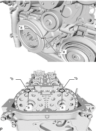
*a Timing Mark *b Paint Mark Align the timing mark of the crankshaft pulley and timing chain cover by rotating the crankshaft clockwise.
-
Make sure that the timing mark of the camshaft timing sprocket is at the top.
Tech Tips
If the timing mark is not at the top, turn the crankshaft pulley 1 revolution so that the timing mark is at the top (set the No. 1 piston to TDC/compression).
-
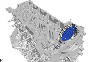
Place paint marks on the No. 2 chain sub-assembly.
-
-
REMOVE NO. 3 CAMSHAFT BEARING CAP
-
Remove the 2 bolts and No. 3 camshaft bearing cap from the cylinder head sub-assembly.
-
-
REMOVE VACUUM PUMP ASSEMBLY
-
REMOVE CAMSHAFT OIL SEAL RETAINER
-
REMOVE TIMING CHAIN GUIDE
-
Remove the bolt and timing chain guide from the cylinder head sub-assembly.
-
-
REMOVE CAMSHAFT
-
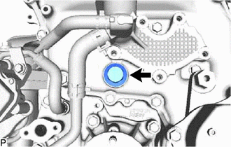
Remove the oil pump relief valve plug and gasket from timing chain cover.
-
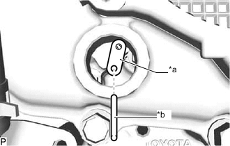
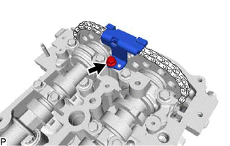
*a Stopper Plate *b Pin Insert a pin into stopper plate hole of the No. 2 chain tensioner assembly and lock the No. 2 chain tensioner assembly.
-
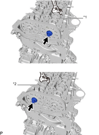
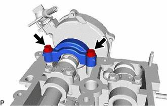
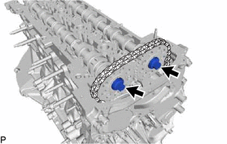
*1 No. 1 Camshaft *2 No. 2 Camshaft Hold the hexagonal portion of the camshaft with a wrench and loosen the 2 bolts from the No. 1 camshaft and No. 2 camshaft.
Note
Be careful not to damage the cylinder head sub-assembly with the wrench.
-
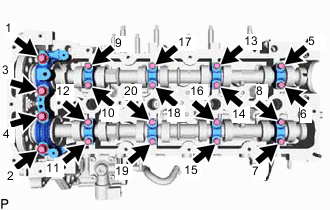
Using several steps, and remove the 20 bolt, No. 1 camshaft bearing cap and 8 No. 2 camshaft bearing caps from the cylinder head sub-assembly.
-
Raise the No. 1 camshaft and remove the bolt from the No. 1 camshaft.
-
Raise the No. 2 camshaft and remove the bolt from the No. 2 camshaft.
-
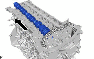
Remove the No. 2 camshaft from the camshaft timing sprocket.
-
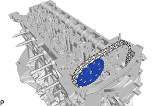
Remove the camshaft timing sprocket from the No. 2 chain sub-assembly.
-
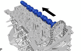
Remove the No. 1 camshaft from the camshaft timing sprocket.
-
Remove the camshaft timing sprocket from the No. 2 chain sub-assembly.
-
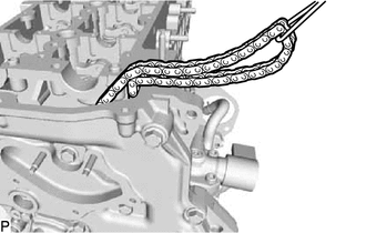
Suspend the No. 2 chain sub-assembly with a string or equivalent.
Tech Tips
Be careful not to drop the No. 2 chain sub-assembly inside the timing chain cover assembly.
-