CAUTION / NOTICE / HINT
-
When replacing the parts in the following chart (A), replace the No. 1 injection pipe sub-assembly, No. 2 injection pipe sub-assembly and/or fuel inlet pipe sub-assembly with new ones.
Replaced Parts (A) Pipes Requiring New Replacement Injector assembly (including shuffling the injector assemblies between the cylinders)
-
No. 1 injection pipe sub-assembly
-
No. 2 injection pipe sub-assembly
-
Supply pump assembly
-
Common rail assembly
-
Cylinder block sub-assembly
-
Cylinder head sub-assembly
-
Cylinder head gasket
-
Timing chain case assembly
-
No. 1 injection pipe sub-assembly
-
No. 2 injection pipe sub-assembly
-
Fuel inlet pipe sub-assembly
-
-
After removing the No. 1 injection pipe sub-assembly, No. 2 injection pipe sub-assembly and/or fuel inlet pipe sub-assembly, clean them with a brush and compressed air.
-
The injector assembly is a precision instrument. Do not use the injector assembly if it is struck or dropped.
-
Make sure foreign matter does not enter the fuel path.
PROCEDURE
- Click here
INSTALL CAMSHAFT
-
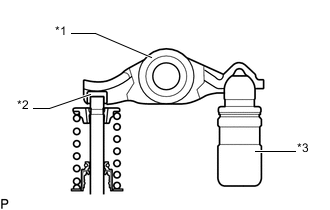
*1 Valve Rocker Arm Sub-assembly *2 Valve Stem Cap *3 Valve Lash adjuster assembly Check that the valve rocker arm sub-assembly is firmly set to the valve lash adjuster assembly.
-
Apply a light coat of engine oil to the camshaft journals of the cylinder head sub-assembly and the thrust portion of the camshaft.
-
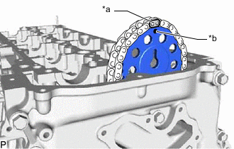
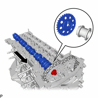
*a Paint Mark *b Timing Mark Align the paint mark of the No. 2 chain sub-assembly and timing mark of the camshaft timing sprocket, and install the camshaft timing sprocket to the No. 2 chain sub-assembly.
Tip:Make sure the timing mark of the camshaft timing sprocket face the front side.
-
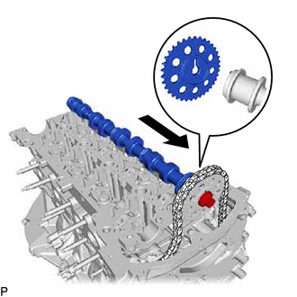
Align the knock pin of the No. 1 camshaft to the groove of the sprocket and install the No. 1 camshaft to the camshaft timing sprocket, and set the bolt.
-
*a Paint Mark *b Timing Mark Align the paint mark of the No. 2 chain sub-assembly and timing mark of the camshaft timing sprocket, and install the camshaft timing sprocket to the No. 2 chain sub-assembly.
Tip:Make sure the timing mark of the camshaft timing sprocket face the front side.
-
Align the knock pin of the No. 2 camshaft to the groove of the sprocket and install the No. 2 camshaft to the camshaft timing sprocket, and set the bolt.
Tip: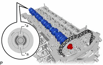
*a Glove Glove is at the rear end of the No. 2 camshaft.
-
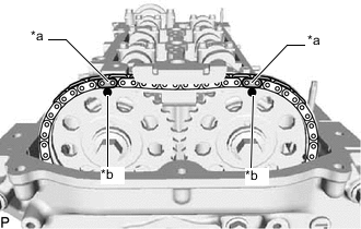
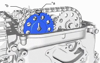
*a Paint Mark *b Timing Mark Check the timing mark of the camshaft timing sprocket and paint mark of the No. 2 chain sub-assembly.
-
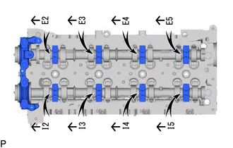
Set the No. 1 camshaft bearing cap and 8 No. 2 camshaft bearing caps to the cylinder head sub-assembly as shown in the illustration.
-
Temporarily install the 20 bolts.
-
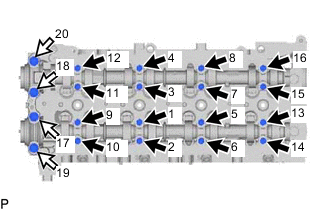

Bolt A 
Bolt B Uniformly tighten the 20 bolts in several steps in the order shown in the illustration.
for bolt A 10 N*m 102 kgf*cm 7 ft.*lbf for bolt B 21 N*m 214 kgf*cm 15 ft.*lbf -
*1 No. 1 Camshaft *2 No. 2 Camshaft Hold the hexagonal portion of the No. 1 camshaft and No. 2 camshaft with a wrench, and tighten the 2 bolts.
81 N*m 826 kgf*cm 60 ft.*lbf Note:Be careful not to damage the cylinder head sub-assembly with the wrench.
-
Remove the pin from the No. 2 chain tensioner assembly.
-
Install a new gasket and the oil pump relief valve plug to the timing chain cover.
46 N*m 469 kgf*cm 34 ft.*lbf
-
- Click here
INSTALL TIMING CHAIN GUIDE
-
Install the timing chain guide to the cylinder head sub-assembly with the bolt.
10 N*m 102 kgf*cm 7 ft.*lbf
-
- Click here
INSTALL CAMSHAFT OIL SEAL RETAINER
- Click here
TEMPORARILY INSTALL VACUUM PUMP ASSEMBLY
- Click here
INSTALL NO. 3 CAMSHAFT BEARING CAP
-
Clean and degrease the contact surfaces of the cylinder head sub-assembly and No. 3 camshaft bearing cap.
-
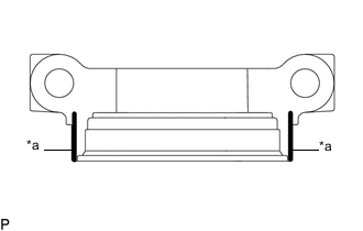
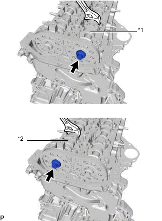
*a Seal Packing Apply seal packing to the specified areas as shown in the illustration.
Seal packing Toyota Genuine Seal Packing Black, Three Bond 1207B or equivalent Standard seal diameter 3.0 mm (0.118 in.) Note:
-
Do not allow seal packing to contact the oil passage of the No. 3 camshaft bearing cap.
-
After applying seal packing, install the No. 3 camshaft bearing cap within 3 minutes and tighten the bolts within 10 minutes.
-
Do not start the engine for at least 2 hours after installation.
-
-
Install the No. 3 camshaft bearing cap with the 2 bolts.
21 N*m 214 kgf*cm 15 ft.*lbf -
Wipe off excess seal packing from between No. 3 camshaft bearing cap and cylinder head sub-assembly.
-
- Click here
INSTALL VACUUM PUMP ASSEMBLY
- Click here
INSTALL CYLINDER HEAD COVER SUB-ASSEMBLY
- Click here
INSTALL NOZZLE HOLDER GASKET
- Click here
TEMPORARILY INSTALL INJECTOR ASSEMBLY
- Click here
TEMPORARILY INSTALL NO. 1 INJECTION PIPE SUB-ASSEMBLY AND NO. 2 INJECTION PIPE SUB-ASSEMBLY
- Click here
TIGHTEN INJECTOR ASSEMBLY
- Click here
TIGHTEN NO. 1 INJECTION PIPE SUB-ASSEMBLY AND NO. 2 INJECTION PIPE SUB-ASSEMBLY
- Click here
INSTALL NOZZLE LEAKAGE PIPE ASSEMBLY
- Click here
INSTALL HARNESS BRACKET
- Click here
INSTALL WIRING HARNESS CLAMP BRACKET
- Click here
INSTALL NO. 1 EGR COOLER AND NO. 2 EGR VALVE ASSEMBLY WITH ELECTRIC EGR CONTROL VALVE ASSEMBLY
- Click here
INSTALL VACUUM CONTROL VALVE SET
- Click here
INSTALL NO. 1 EGR PIPE SUB-ASSEMBLY (w/o DPF)
- Click here
INSTALL EGR PIPE WITH COOLER SUB-ASSEMBLY (w/ DPF)
- Click here
CONNECT NO. 4 WATER BY-PASS PIPE SUB-ASSEMBLY
- Click here
INSTALL NO. 3 WATER BY-PASS PIPE SUB-ASSEMBLY
- Click here
INSTALL NO. 2 EGR PIPE
- Click here
INSTALL EGR VALVE BRACKET
- Click here
CONNECT ENGINE WIRE
- Click here
INSTALL NO. 1 UREA TANK FILLER PIPE SUPPORT (w/ Urea SCR System)
- Click here
CONNECT UREA TANK FILLER PIPE ASSEMBLY (w/ Urea SCR System)
- Click here
CONNECT FUEL FILTER ASSEMBLY
- Click here
INSTALL NO. 2 ENGINE COVER BRACKET
- Click here
INSTALL NO. 2 HOSE TO HOSE TUBE
- Click here
INSTALL TURBO PRESSURE SENSOR
- Click here
INSTALL GAS FILTER
- Click here
INSTALL NO. 1 FUEL PIPE (w/ DPF)
- Click here
INSTALL NO. 2 WATER BY-PASS PIPE
- Click here
INSTALL DIESEL THROTTLE BODY ASSEMBLY
- Click here
INSTALL INTERCOOLER AIR TUBE
- Click here
INSTALL NO. 4 AIR HOSE
- Click here
INSTALL RADIATOR ASSEMBLY
- Click here
CONNECT NO. 2 RADIATOR HOSE
- Click here
INSTALL FAN SHROUD
- Click here
CONNECT NO. 1 OIL COOLER INLET HOSE (for Automatic Transmission)
- Click here
CONNECT NO. 1 OIL COOLER OUTLET HOSE (for Automatic Transmission)
- Click here
INSTALL RADIATOR RESERVE TANK ASSEMBLY
- Click here
INSTALL NO. 1 OIL RESERVOIR BRACKET
- Click here
CONNECT VANE PUMP OIL RESERVOIR ASSEMBLY
- Click here
INSTALL NO. 1 RADIATOR HOSE
- Click here
INSTALL NO. 2 AIR TUBE
- Click here
INSTALL NO. 4 AIR HOSE
- Click here
INSTALL NO. 1 RADIATOR AIR GUIDE
- Click here
INSTALL NO. 1 ENGINE COVER SUB-ASSEMBLY
- Click here
INSTALL FRONT BUMPER
- Click here
INSTALL NO. 1 ENGINE UNDER COVER ASSEMBLY (for 4WD and Pre-Runner)
- Click here
CONNECT CABLE TO NEGATIVE BATTERY TERMINAL
Note:When disconnecting the cable, some systems need to be initialized after the cable is reconnected.
- Click here
ADD ENGINE COOLANT
- Click here
INSPECT FOR COOLANT LEAK
- Click here
BLEED AIR FROM FUEL SYSTEM
- Click here
INSPECT FOR FUEL LEAK