PROCEDURE
- Click here
REPLACE VALVE STEM OIL SEAL
-
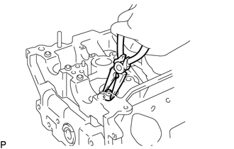
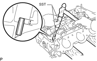
Using needle-nose pliers, remove the valve stem oil seal.
-
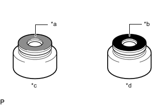
*a Gray *b Black *c Intake Side *d Exhaust Side Apply a light coat of engine oil to the valve stem oil seal.
Note:Make sure that the body identification colors of the valve stem oil seals are matching.
-
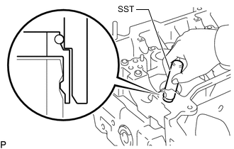
Using SST and a hammer, push in a new valve stem oil seal.
09201-41020
-
- Click here
REPLACE VALVE GUIDE BUSH
-
Heat the cylinder head to approximately 80 to 100°C (176 to 212°F).
CAUTION:Be sure to wear protective gloves.
-
Place the cylinder on wooden blocks.
-
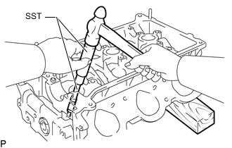
Using SST and a hammer, tap out the intake valve guide bush from the cylinder head.
09201-10000 09201-01055 09950-70010 09951-07100 -
Using a caliper gauge, measure the valve guide bush bore diameter of the cylinder head.
Standard Bush Bore Diameter Item Specified Condition STD 10.285 to 10.306 mm (0.405 to 0.406 in.) O/S 0.05 10.335 to 10.356 mm (0.407 to 0.408 in.) If the valve guide bush bore diameter of the cylinder head is more than 10.306 mm (0.406 in.), machine the valve guide bush bore diameter to between 10.335 and 10.356 mm (0.407 and 0.408 in.).
If the valve guide bush bore diameter of the cylinder head is more than 10.356 mm (0.408 in.), replace the cylinder head.
-
Select a new valve guide bush (STD or O/S 0.05).
Valve Guide Bush Bush Size Specified Condition Use STD 10.333 to 10.344 mm (0.4068 to 0.4072 in.) Use O/S 0.05 10.383 to 10.394 mm (0.4088 to 0.4092 in.) Tip:Table 1. Standard Bush Length Item Specified Condition Intake side 34.3 to 34.7 mm (1.35 to 1.37 in.) Exhaust side 40.3 to 40.7 mm (1.59 to 1.60 in.) -
Heat the cylinder head to approximately 80 to 100°C (176 to 212°F).
CAUTION:Be sure to wear protective gloves.
-
Place the cylinder head on wooden blocks.
-
Using SST and a hammer, tap in a new valve guide bush to the specified protrusion height.
09201-10000 09201-01055 09950-70010 09951-07100 Standard protrusion height 9.3 to 9.7 mm (0.366 to 0.382 in.) -
Using a sharp 5.5 mm reamer, ream the valve guide bush to obtain the standard specified clearance between the valve guide bush and valve stem.
Standard Oil Clearance Item Specified Condition Intake side 0.025 to 0.060 mm (0.000984 to 0.00236 in.) Exhaust side 0.030 to 0.065 mm (0.00118 to 0.00256 in.)
-
- Click here
REPLACE UNION
Tip:Perform this procedure only when replacement of the union is necessary.
-
Remove the unions from the cylinder head sub-assembly (front side) and cylinder head LH (intake port side).
-
Apply adhesive to 2 or 3 threads of the bolt ends of new unions.
Adhesive Toyota Genuine Seal Adhesive 1324, Three Bond 1324 or equivalent -
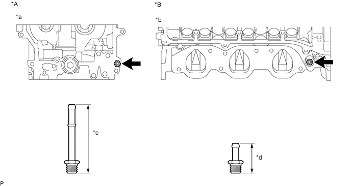
*A for Bank 1 *B for Bank 2 *a Front Side *b Intake Port Side *c 67 mm (2.64 in.) *d 30 mm (1.18 in.) Using a 12 mm deep socket wrench, install the 2 unions.
14.7 N*m 150 kgf*cm 11 ft.*lbf
-
- Click here
REPLACE NO. 1 STRAIGHT SCREW PLUG
Note:It is not necessary to remove the No. 1 straight screw plug unless it is being replaced.
-
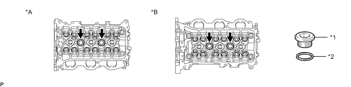
*A for Bank 1 *B for Bank 2 *1 No. 1 Straight Screw Plug *2 Gasket Using a 14 mm hexagon wrench, remove the No. 1 straight screw plug and gasket.
-
Using a 14 mm hexagon wrench, install a new gasket and No. 1 straight screw plug.
80 N*m 816 kgf*cm 59 ft.*lbf
-
- Click here
REPLACE NO. 2 STRAIGHT SCREW PLUG
Note:It is not necessary to remove the No. 2 straight screw plug plug unless it is being replaced.
-
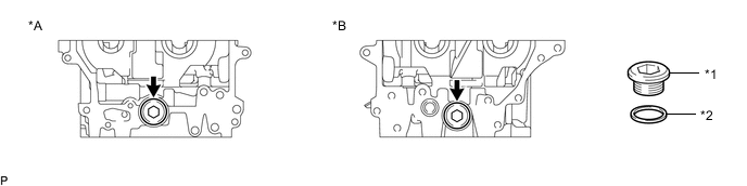
*A for Bank 1 *B for Bank 2 *1 No. 2 Straight Screw Plug *2 Gasket Using a 14 mm hexagon wrench, remove the No. 2 straight screw plug and gasket.
-
Using a 14 mm hexagon wrench, install a new gasket and No. 2 straight screw plug.
85 N*m 867 kgf*cm 63 ft.*lbf
-
- Click here
REPLACE RING PIN
Note:It is not necessary to remove the ring pin unless it is being replaced.
-
Remove the ring pins.
-
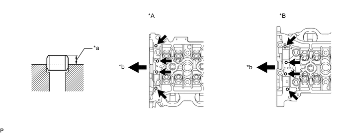
*A for Bank 1 *B for Bank 2 *a Protrusion Height *b Engine Front Using a plastic-faced hammer, tap in new ring pins until they reach the standard protrusion height.
Standard protrusion height 2.7 to 3.3 mm (0.106 to 0.130 in.)
-
- Click here
REPLACE STRAIGHT PIN
Note:It is not necessary to remove the straight pin unless it is being replaced.
-
Remove the straight pins.
-
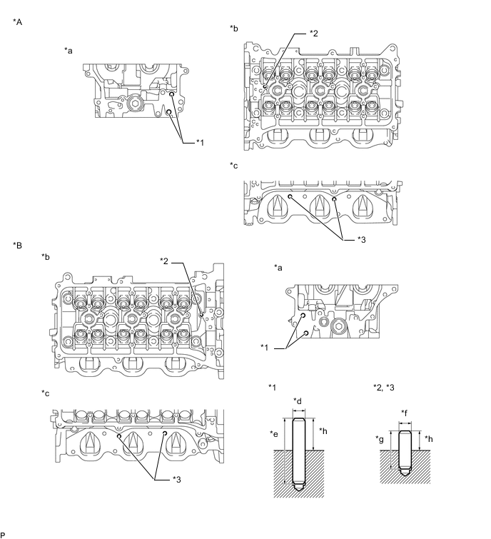
*A for Bank 1 *B for Bank 2 *1 Straight Pin A *2 Straight Pin B *3 Straight Pin C - - *a Front Side *b Upper Side *c Intake Manifold Side *d 8.0 mm (0.315 in.) *e 34.0 mm (1.34 in.) *f 5.0 mm (0.197 in.) *g 13.8 mm (0.543 in.) *h Protrusion Height Using a plastic-faced hammer, tap in new straight pins until they reach the standard protrusion height.
Standard Protrusion Height Item Specified Condition Straight pin A 17.5 to 19.5 mm (0.689 to 0.768 in.) Straight pin B 7.5 to 8.5 mm (0.295 to 0.335 in.) Straight pin C 7.0 to 9.0 mm (0.276 to 0.354 in.)
-
- Click here
REPLACE STUD BOLT
Note:If a stud bolt is deformed or its threads are damaged, replace it.
-
Using an E6 and E7 "TORX" socket wrench, remove the stud bolts.
-
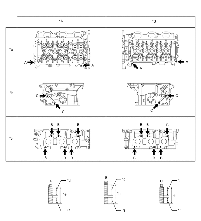
*A for Bank 1 *B for Bank 2 *a Upper Side *b Rear Side *c Exhaust Manifold Side *d 21 mm (0.827 in.) *e 34 mm (1.34 in.) *f 9 mm (0.354 in.) *g 20 mm (0.787 in.) *h 35 mm (1.38 in.) *i 13 mm (0.512 in.) *j 16 mm (0.630 in.) *k 27 mm (1.06 in.) - - Using an E6 and E7 "TORX" socket wrench, install new stud bolts.
for stud bolt A 4.0 N*m 41 kgf*cm 35 in.*lbf for stud bolt B 9.5 N*m 97 kgf*cm 84 in.*lbf for stud bolt C 4.0 N*m 41 kgf*cm 35 in.*lbf
-