ENGINE UNIT INSTALLATION

PROCEDURE
-
INSTALL NO. 1 IDLER PULLEY SUB-ASSEMBLY
-
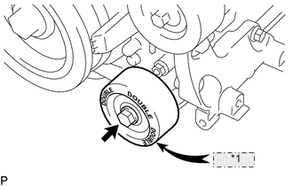
*1 "DOUBLE" Install the No. 1 idler pulley sub-assembly with the bolt.
- Torque:
- 54 N*m { 551 kgf*cm, 40 ft.*lbf }
Note
-
Do not mistakenly install the No. 2 idler pulley sub-assembly instead of the No. 1 idler pulley sub-assembly.
-
The No. 1 idler pulley sub-assembly has a "DOUBLE" mark.
-
-
INSTALL NO. 2 IDLER PULLEY SUB-ASSEMBLY
-
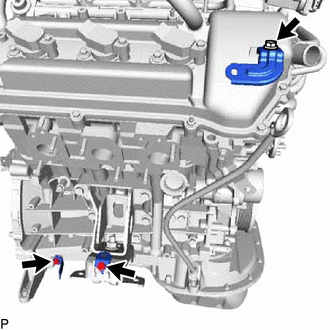
INSTALL ENGINE OIL LEVEL DIPSTICK GUIDE
-
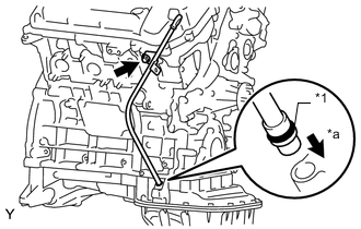
*1 O-Ring *a Push Install a new O-ring to the engine oil level dipstick guide.
-
Apply a light coat of engine oil to the O-ring.
-
Push in the engine oil level dipstick guide end into the guide hole of the oil pan sub-assembly.
-
Install the engine oil level dipstick guide with the bolt.
- Torque:
- 9.0 N*m { 92 kgf*cm, 80 in.*lbf }
-
Install the engine oil level dipstick.
-
-
INSTALL IGNITION COIL ASSEMBLY
-
INSTALL INTAKE MANIFOLD
-
INSTALL FUEL INJECTOR ASSEMBLY
-
INSTALL FUEL DELIVERY PIPE SUB-ASSEMBLY
-
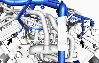
INSTALL V-RIBBED BELT TENSIONER ASSEMBLY
-
Temporarily install the V-ribbed belt tensioner assembly with the 5 bolts.
-
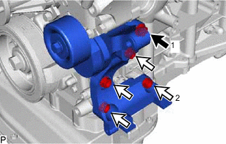

Bolt A 
Bolt B Tighten bolts 1 and 2 in numerical order.
- Torque:
- 36 N*m { 367 kgf*cm, 27 ft.*lbf }
-
Tighten the other bolts.
- Torque:
- 36 N*m { 367 kgf*cm, 27 ft.*lbf }
Standard Bolt Length Item Specified Condition Bolt A 70 mm (2.76 in.) Bolt B 33 mm (1.30 in.)
-
-
INSTALL FRONT NO. 1 ENGINE MOUNTING BRACKET LH
-
Install the front No. 1 engine mounting bracket LH with the 3 bolts.
- Torque:
- 43 N*m { 438 kgf*cm, 32 ft.*lbf }
-
-
INSTALL FRONT NO. 1 ENGINE MOUNTING BRACKET RH
-
Install the front No. 1 engine mounting bracket RH with the 4 bolts.
- Torque:
- 43 N*m { 438 kgf*cm, 32 ft.*lbf }
-
-
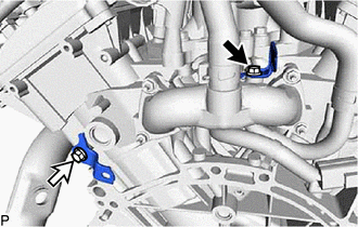
INSTALL NO. 1 FUEL PIPE SUB-ASSEMBLY AND NO. 2 FUEL PIPE SUB-ASSEMBLY
-
Install the No. 1 fuel pipe sub-assembly and No. 2 fuel pipe sub-assembly with the 2 bolts.
- Torque:
- 9.0 N*m { 92 kgf*cm, 80 in.*lbf }
-
Connect the No. 2 fuel pipe sub-assembly and install the No. 2 fuel pipe clamp to the fuel pressure regulator assembly.
-
Connect the No. 1 fuel pipe sub-assembly and install the No. 2 fuel pipe clamp to the fuel delivery pipe sub-assembly.
-
-
INSTALL NO. 2 PCV HOSE
-
INSTALL PCV HOSE
-
INSTALL WATER HOSE SUB-ASSEMBLY
-
Install the water hose sub-assembly, and slide the 2 clamps to secure the hose.
-
-
INSTALL WIRE HARNESS CLAMP BRACKET
-
for LH Side:
-
Install the wire harness clamp bracket with the bolt.
- Torque:
- 13 N*m { 133 kgf*cm, 10 ft.*lbf }
-
-
for RH Side:
-
Install the 3 wire harness clamp brackets with the 3 bolts.
- Torque:
- 13 N*m { 133 kgf*cm, 10 ft.*lbf }
-
-
Bolt A Bolt B for Rear Side:
-
Install the 2 wire harness clamp brackets with the 2 bolts.
- Torque:
- for bolt A
- 13 N*m { 133 kgf*cm, 10 ft.*lbf }
- for bolt B
- 31 N*m { 316 kgf*cm, 23 ft.*lbf }
-
-
-
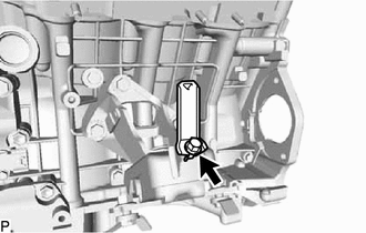
INSTALL ENGINE WIRE
-
Install the wire harness with the 2 bolts to the engine as shown in the illustration.
- Torque:
- 10 N*m { 102 kgf*cm, 7 ft.*lbf }
-
Connect the connectors and wire harness to the engine.
-