ENGINE UNIT DISASSEMBLY

PROCEDURE
-
REMOVE ENGINE OIL PRESSURE SWITCH ASSEMBLY
-
REMOVE ENGINE COOLANT TEMPERATURE SENSOR
-
REMOVE CYLINDER BLOCK WATER DRAIN COCK SUB-ASSEMBLY
-
Remove the cylinder block water drain cock sub-assembly.
-
Remove the cylinder block water drain cock plug from the cylinder block water drain cock sub-assembly.
-
-
REMOVE VVT SENSOR (for Bank 1)
-
REMOVE VVT SENSOR (for Bank 2)
-
REMOVE CRANKSHAFT POSITION SENSOR
-
REMOVE CAMSHAFT TIMING OIL CONTROL VALVE ASSEMBLY (for Bank 1)
-
REMOVE CAMSHAFT TIMING OIL CONTROL VALVE ASSEMBLY (for Bank 2)
-
REMOVE OIL CONTROL VALVE FILTER
-
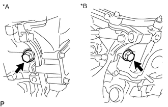
*A for Bank 1 *B for Bank 2 Remove the 2 unions, 2 oil control valve filters and 2 gaskets.
-
-
REMOVE OIL FILTER SUB-ASSEMBLY
-
REMOVE OIL COOLER ASSEMBLY
-
REMOVE OIL FILTER BRACKET SUB-ASSEMBLY
-
REMOVE WATER INLET ASSEMBLY
-
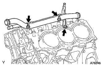
REMOVE REAR WATER BY-PASS JOINT
-
Remove the 2 bolts, 4 nuts, rear water by-pass joint and 2 gaskets.
-
Remove the O-ring from the No. 1 water outlet pipe.
-
-
REMOVE OIL FILLER CAP SUB-ASSEMBLY
-
Remove the oil filler cap sub-assembly.
-
Remove the gasket from the oil filler cap sub-assembly.
-
-
REMOVE OIL FILLER CAP HOUSING
-
Remove the 2 nuts, oil filler cap housing and gasket.
-
-
REMOVE SPARK PLUG
-
REMOVE CYLINDER HEAD COVER SUB-ASSEMBLY
-
REMOVE PCV VALVE SUB-ASSEMBLY
-
REMOVE CYLINDER HEAD COVER SUB-ASSEMBLY LH
-
SET NO. 1 CYLINDER TO TDC/COMPRESSION
-
REMOVE CRANKSHAFT PULLEY
-
REMOVE OIL PAN DRAIN PLUG
-
Remove the oil pan drain plug and gasket.
-
-
REMOVE NO. 2 OIL PAN SUB-ASSEMBLY
-
REMOVE OIL STRAINER SUB-ASSEMBLY
-
REMOVE OIL PAN SUB-ASSEMBLY
-
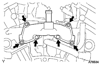
REMOVE ENGINE REAR OIL SEAL RETAINER
-
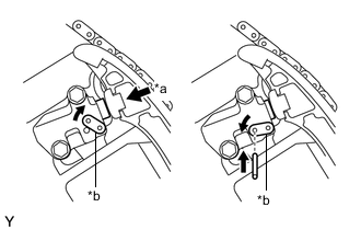
*a Pry *b Protective Tape Remove the 5 bolts and 2 nuts.
-
Using a screwdriver, remove the engine rear oil seal retainer by prying between the engine rear oil seal retainer and crankshaft bearing cap.
Tech Tips
Tape the screwdriver tip before use.
-
-
REMOVE REAR CRANKSHAFT OIL SEAL
-
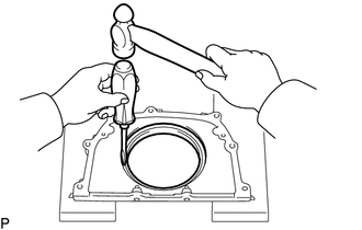
Using a screwdriver and hammer, tap out the rear crankshaft oil seal.
Note
Be careful not to damage the engine rear oil seal retainer.
-
-
REMOVE TIMING CHAIN COVER SUB-ASSEMBLY
-
REMOVE ENGINE WATER PUMP ASSEMBLY
-
Remove the 8 bolts, engine water pump assembly and gasket.
-
-
REMOVE TIMING CHAIN COVER PLATE
-
REMOVE FRONT CRANKSHAFT OIL SEAL
-
REMOVE NO. 1 CHAIN TENSIONER ASSEMBLY
Note
-
Never rotate the crankshaft with the No. 1 chain tensioner assembly removed.
-
When rotating the camshaft with the timing chain removed, rotate the crankshaft counterclockwise 40° from TDC first.
-
*a Push *b Stopper Plate While turning the stopper plate of the No. 1 chain tensioner assembly clockwise, push in the plunger of the No. 1 chain tensioner assembly as shown in the illustration.
-
While turning the stopper plate of the No. 1 chain tensioner assembly counterclockwise, insert a bar with a diameter of 3.5 mm (0.138 in.) into the holes in the stopper plate and No. 1 chain tensioner assembly to fix the stopper plate in place.
-
Remove the 2 bolts and No. 1 chain tensioner assembly.
-
-
REMOVE CHAIN TENSIONER SLIPPER
-
REMOVE IDLE SPROCKET ASSEMBLY
-
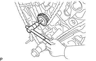
Using a 10 mm hexagon wrench, remove the No. 2 idle gear shaft, idle sprocket assembly and No. 1 idle gear shaft.
-
-
REMOVE NO. 2 CHAIN VIBRATION DAMPER
-
Remove the 2 No. 2 chain vibration dampers.
-
-
REMOVE CHAIN SUB-ASSEMBLY
-
REMOVE CRANKSHAFT TIMING SPROCKET
-
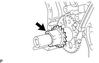
Remove the crankshaft timing sprocket.
-
-
REMOVE NO. 1 CHAIN VIBRATION DAMPER
-
Remove the 2 bolts and No. 1 chain vibration damper.
-
-
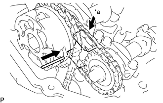
REMOVE CAMSHAFT TIMING GEARS AND NO. 2 CHAIN SUB-ASSEMBLY (for Bank 1)
-
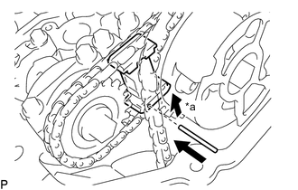
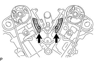
*a Raise While raising the No. 2 chain tensioner assembly, insert a pin with a diameter of 1.0 mm (0.0394 in.) into the hole to fix the No. 2 chain tensioner assembly in place.
-
Hold the hexagonal portion of the No. 2 camshaft with a wrench and remove the 2 bolts, camshaft timing gear sub-assembly, camshaft timing sprocket and No. 2 chain sub-assembly.
Note
-
Do not damage the surrounding parts.
-
Do not disassemble the camshaft timing gear sub-assembly.
-
-
-
REMOVE NO. 2 CHAIN TENSIONER ASSEMBLY
-
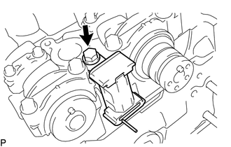
Remove the bolt and No. 2 chain tensioner assembly.
-
-
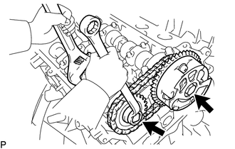
REMOVE CAMSHAFT TIMING GEARS AND NO. 2 CHAIN SUB-ASSEMBLY (for Bank 2)
-
*a Push While raising the No. 3 chain tensioner assembly, insert a pin with a diameter of 1.0 mm (0.0394 in.) into the hole to fix the No. 3 chain tensioner assembly in place.
-
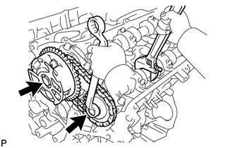
Hold the hexagonal portion of the No. 4 camshaft sub-assembly with a wrench and remove the 2 bolts, camshaft timing gear sub-assembly, camshaft timing sprocket and No. 2 chain sub-assembly.
Note
-
Do not damage the surrounding parts.
-
Do not disassemble the camshaft timing gear sub-assembly.
-
-
-
REMOVE NO. 3 CHAIN TENSIONER ASSEMBLY
-
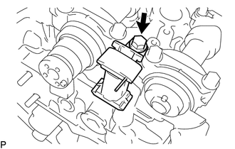
Remove the bolt and No. 3 chain tensioner assembly.
-
-
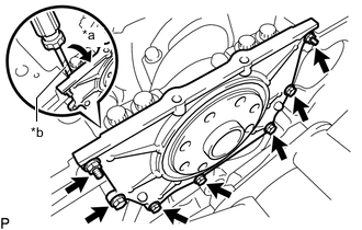
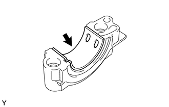
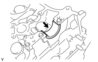
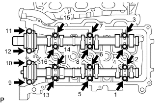
REMOVE CAMSHAFT BEARING CAP (for Bank 1)
Note
As the thrust clearance of the camshaft is small, the camshaft must be kept level while it is being removed. If the camshaft is not kept level, the portion of the cylinder head which receives the shaft thrust may crack or be damaged, causing the camshaft to seize or break. To avoid this, make sure the following steps are carried out.
-
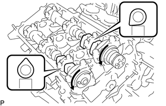
Rotate the camshaft and No. 2 camshaft counterclockwise and set the camshaft and No. 2 camshaft as shown in the illustration.
-
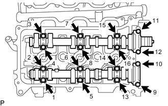
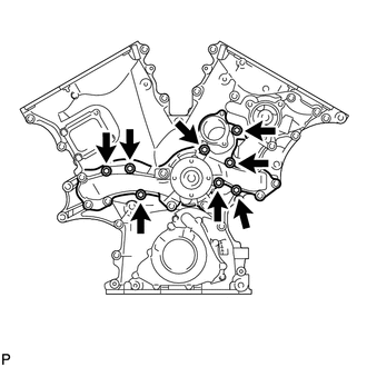
Uniformly loosen the 16 bolts in the sequence shown in the illustration and remove the bolts and 8 camshaft bearing caps.
-
-
REMOVE CAMSHAFT
-
REMOVE NO. 2 CAMSHAFT
-
REMOVE NO. 1 CAMSHAFT BEARING
-
REMOVE NO. 2 CAMSHAFT BEARING
-
REMOVE CAMSHAFT BEARING CAP (for Bank 2)
-
Uniformly loosen the 16 bolts in the sequence shown in the illustration and remove the bolts and 8 camshaft bearing caps.
-
-
REMOVE NO. 3 CAMSHAFT SUB-ASSEMBLY
-
REMOVE NO. 4 CAMSHAFT SUB-ASSEMBLY
-
REMOVE CYLINDER HEAD SUB-ASSEMBLY
-
REMOVE CYLINDER HEAD GASKET
-
REMOVE CYLINDER HEAD LH
-
REMOVE NO. 2 CYLINDER HEAD GASKET
-
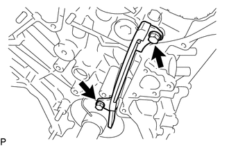
REMOVE NO. 1 WATER OUTLET PIPE
-
Remove the knock sensor wire.
-
for Type A:
Remove the 3 bolts and No. 1 water outlet pipe.
-
for Type B:
Remove the bolt, 2 nuts and No. 1 water outlet pipe.
-
-
REMOVE KNOCK SENSOR
-
REMOVE VALVE LIFTER
-
Remove the 24 valve lifters.
Tech Tips
Arrange the removed parts so that they can be reinstalled in their original locations.
-
-
REMOVE TAPER SCREW PLUG
Note
It is not necessary to remove a taper screw plug unless it is being replaced.
-
REMOVE STUD BOLT
Note
If a stud bolt is deformed or its threads are damaged, replace it.