CAUTION / NOTICE / HINT
The necessary procedures (adjustment, calibration, initialization, or registration) that must be performed after parts are removed, installed, or replaced during the cylinder block removal/installation are shown below.
| Replacement Part or Procedure | Necessary Procedures | Effects/Inoperative when not Performed | Link |
|---|---|---|---|
| Replacement of piston or piston ring | Inspection after repair | Poor idle, engine start, etc. |
PROCEDURE
- Click here
INSPECT CONNECTING ROD THRUST CLEARANCE
-
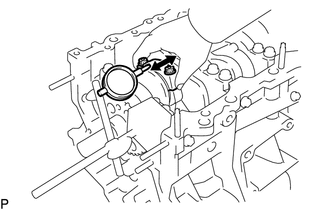
Using a dial indicator, measure the thrust clearance while moving the connecting rod back and forth.
Standard thrust clearance 0.15 to 0.30 mm (0.00591 to 0.0118 in.) Maximum thrust clearance 0.35 mm (0.0138 in.) If the thrust clearance is more than the maximum, inspect the connecting rod sub-assembly and crankshaft.
-
- Click here
INSPECT CONNECTING ROD OIL CLEARANCE
-
Uniformly loosen the 2 connecting rod bolts and remove the connecting rod cap together with the connecting rod bearing.
-
Clean the crank pin and bearing.
-
Check the crank pin and bearing for pitting and scratches. If the crank pin or bearing is damaged, replace the bearings. If necessary, replace the crankshaft.
-
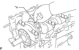
*a Plastigage Lay a strip of Plastigage across the crank pin.
Note:Do not turn the crankshaft.
-
Install the connecting rod bearing cap.
-
Uniformly loosen the 2 connecting rod bolts and remove the connecting rod cap together with the connecting rod bearing.
-
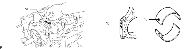
*a Plastigage *b Number Mark Measure the Plastigage at its widest point.
Standard oil clearance 0.040 to 0.066 mm (0.00157 to 0.00260 in.) Maximum oil clearance 0.086 mm (0.00399 in.) If the clearance is the maximum or more, select and replace the connecting rod bearing or replace the crankshaft.
Tip:If replacing a bearing, replace it with one that has the same number marked on the connecting rod. There are 4 sizes of standard bearings, marked "1 ", "2", "3" and "4" accordingly.
Standard Bearing Center Wall Thickness Item Specified Condition Mark 1 1.484 to 1.487 mm (0.05843 to 0.05854 in.) Mark 2 1.487 to 1.490 mm (0.05854 to 0.05866 in.) Mark 3 1.490 to 1.493 mm (0.05866 to 0.05878 in.) Mark 4 1.493 to 1.496 mm (0.05878 to 0.05900 in.) -
Completely remove the Plastigage.
-
- Click here
REMOVE PISTON WITH CONNECTING ROD
-
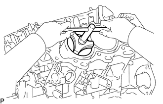
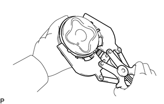
Using a ridge reamer, remove all the carbon from the top of the cylinder.
-
Push out the piston with connecting rod from the cylinder block sub-assembly.
Tip:Arrange the removed parts so that they can be reinstalled in their original locations.
-
- Click here
REMOVE CONNECTING ROD BEARING
-
Remove the connecting rod bearing from the connecting rod sub-assembly and connecting rod bearing cap.
Tip:Arrange the removed parts so that they can be reinstalled in their original locations.
-
- Click here
REMOVE PISTON RING SET
Tip:Arrange the removed parts so that they can be reinstalled in their original locations.
-
Using a piston ring expander, remove the No. 1 compression ring and No. 2 compression ring.
-
Remove the 2 oil rings (side rail) and oil ring (expander) by hand.
-
- Click here
REMOVE PISTON PIN HOLE SNAP RING
-
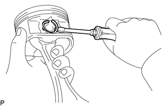
Using a screwdriver, pry out the 2 piston pin hole snap rings.
-
- Click here
REMOVE PISTON WITH PIN SUB-ASSEMBLY
-
Gradually heat the piston to approximately 80°C (176°F).
-
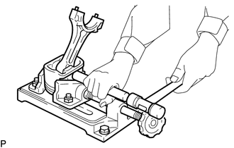
Using a plastic-faced hammer and brass bar, lightly tap out the piston pin and remove the connecting rod sub-assembly.
Tip:Arrange the removed parts so that they can be reinstalled in their original locations.
-
- Click here
INSPECT CRANKSHAFT THRUST CLEARANCE
-
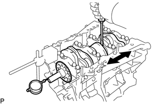
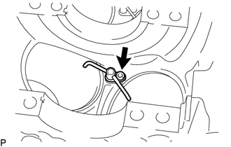
Using a dial indicator, measure the crankshaft thrust clearance while prying the crankshaft back and forth with a screwdriver.
Standard thrust clearance 0.04 to 0.24 mm (0.00157 to 0.00945 in.) Maximum thrust clearance 0.30 mm (0.0118 in.) If the thrust clearance is more than the maximum, replace the thrust washers as a set.
Standard thrust washer thickness 1.93 to 1.98 mm (0.0760 to 0.0780 in.) If necessary, replace the crankshaft.
-
- Click here
REMOVE CRANKSHAFT BEARING CAP
-
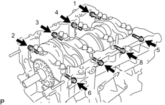
Uniformly loosen the 8 bolts in several steps in the sequence shown in the illustration and remove the 8 bolts and 8 seal washers.
-
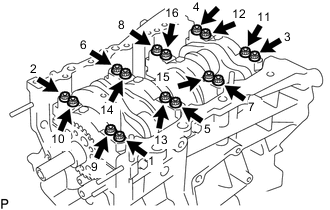
Uniformly loosen the 16 crankshaft bearing cap set bolts in several steps in the sequence shown in the illustration and remove the crankshaft bearing cap set bolts.
-
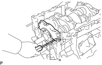
*a Protective Tape Using a screwdriver, pry out the crankshaft bearing caps. Remove the 4 crankshaft bearing caps and lower crankshaft bearings.
Note:
-
Push up on the crankshaft bearing cap little by little, alternating between the right and left sides until the crankshaft bearing cap can be removed.
-
Be careful not to damage the joint surfaces of the cylinder block sub-assembly and crankshaft bearing cap.
Tip:Tape the screwdriver tip before use.
-
-
- Click here
REMOVE CRANKSHAFT
-
Remove the crankshaft.
-
- Click here
REMOVE CRANKSHAFT THRUST WASHER
-
Remove the 2 upper crankshaft thrust washers and 2 lower upper crankshaft thrust washers.
-
- Click here
REMOVE CRANKSHAFT BEARING
-
Remove the upper crankshaft bearing and lower upper crankshaft bearing.
-
- Click here
REMOVE NO. 1 OIL NOZZLE SUB-ASSEMBLY
-
Using a 5 mm hexagon socket wrench, remove the 3 bolts and 3 No. 1 oil nozzle sub-assemblies.
-