CYLINDER HEAD GASKET INSTALLATION
PROCEDURE
-
INSTALL NO. 2 CYLINDER HEAD GASKET
-
Clean and degrease the contact surfaces of the cylinder head LH and cylinder block sub-assembly.
-
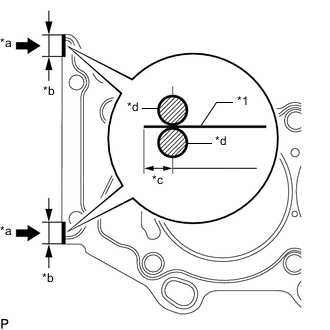
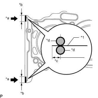
*1 No. 2 Cylinder Head Gasket *a Seal Packing Application Range *b 10 to 15 mm (0.394 to 0.591 in.) *c 1.25 to 1.5 mm (0.0492 to 0.0591 in.) *d Seal Packing Apply seal packing to a new No. 2 cylinder head gasket as shown in the illustration.
Seal packing Toyota Genuine Seal Packing Black, Three Bond 1207B or equivalent Standard seal diameter 2.5 to 3.0 mm (0.0984 to 0.118 in.) Note
-
Install the No. 2 cylinder head gasket within 3 minutes after applying the seal packing.
-
Do not add engine oil within 2 hours of installation.
-
-
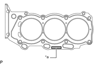
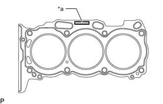
*a Lot No. Stamp Place the No. 2 cylinder head gasket on the cylinder block sub-assembly surface with the front face of the Lot No. stamp upward.
Note
Pay attention to the installation direction.
-
-
INSTALL CYLINDER HEAD LH
-
Place the cylinder head LH on the No. 2 cylinder head gasket.
Note
-
Make sure that no oil is on the mounting surface of the cylinder head LH.
-
Do not damage the cylinder head LH and No. 2 cylinder head gasket.
-
-
Apply a light coat of engine oil to the threads and under the heads of the cylinder head set bolts.
-
Install the 8 cylinder head set bolts and 8 plate washers.
Note
-
Install the cylinder head set bolts to their original positions.
-
Do not drop the plate washer for the cylinder head set bolt into the cylinder head LH.
-
The cylinder head set bolts are tightened in 2 progressive steps.
-
If any cylinder head set bolt is broken or deformed, replace it.
-
-
Step 1:
-
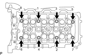
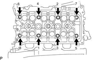
Using a 10 mm bi-hexagon wrench, install and uniformly tighten the 8 cylinder head set bolts with plate washers in several steps in the sequence shown in the illustration.
- Torque:
- 36 N*m { 367 kgf*cm, 27 ft.*lbf }
If any one of the cylinder head set bolts does not meet the torque specification, replace the cylinder head set bolt.
-
-
Step 2:
-
Mark the engine front side of each cylinder head set bolt head with paint.
-
Tighten the cylinder head set bolts 180° in the sequence shown in step 1.
-
-
Check that the painted marks are now facing rearward.
-
Apply a light coat of engine oil to the threads of the bolts.
-
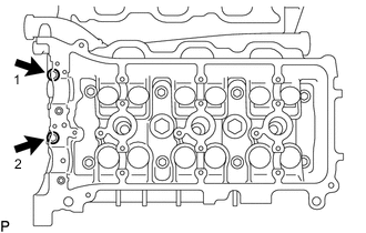
Install the 2 bolts. Using several steps, tighten the bolts uniformly in the sequence shown in the illustration.
- Torque:
- 30 N*m { 306 kgf*cm, 22 ft.*lbf }
-
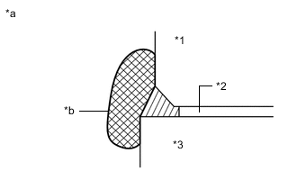
*1 Cylinder Head LH *2 No. 2 Cylinder Head Gasket *3 Cylinder Block Sub-assembly *a Engine Front Side *b Wipe Clean Seal packing will seep out from the front side of the engine. Thoroughly wipe off the seal packing that seeps out.
-
-
INSTALL CYLINDER HEAD GASKET
-
Clean and degrease the contact surfaces of the cylinder head sub-assembly and cylinder block sub-assembly.
-
*1 Cylinder Head Gasket *a Seal Packing Application Range *b 10 to 15 mm (0.394 to 0.591 in.) *c 1.25 to 1.5 mm (0.0492 to 0.0591 in.) *d Seal Packing Apply seal packing to a new cylinder head gasket as shown in the illustration.
Seal packing Toyota Genuine Seal Packing Black, Three Bond 1207B or equivalent Standard seal diameter 2.5 to 3.0 mm (0.0984 to 0.118 in.) Note
-
Install the cylinder head gasket within 3 minutes after applying the seal packing.
-
Do not add engine oil within 2 hours of installation.
-
-
*a Lot No. Stamp Place the cylinder head gasket on the cylinder block sub-assembly surface with the front face of the Lot No. stamp upward.
Note
Pay attention to the installation direction.
-
-
INSTALL CYLINDER HEAD SUB-ASSEMBLY
Tech Tips
Perform "Inspection After Repairs" after replacing the cylinder head sub-assembly.
-
Place the cylinder head sub-assembly on the cylinder head gasket.
Note
-
Make sure that no oil is on the mounting surface of the cylinder head sub-assembly.
-
Do not damage the cylinder head sub-assembly and cylinder head gasket.
-
-
Apply a light coat of engine oil to the threads and under the heads of the cylinder head set bolts.
-
Install the 8 cylinder head set bolts and 8 plate washers.
Note
-
Install the cylinder head set bolts to their original positions.
-
Do not drop the plate washer for the cylinder head set bolt into the cylinder head sub-assembly.
-
The cylinder head set bolts are tightened in 2 progressive steps.
-
If any cylinder head set bolt is broken or deformed, replace it.
-
-
Step 1:
-
Using a 10 mm bi-hexagon wrench, install and uniformly tighten the 8 cylinder head set bolts with plate washers in several steps in the sequence shown in the illustration.
- Torque:
- 36 N*m { 367 kgf*cm, 27 ft.*lbf }
If any one of the cylinder head set bolts does not meet the torque specification, replace the cylinder head set bolt.
-
-
Step 2:
-
Mark the engine front side of each cylinder head set bolt head with paint.
-
Tighten the cylinder head set bolts 180° in the sequence shown in step 1.
-
-
Check that the painted marks are now facing rearward.
-
*1 Cylinder Head Sub-assembly *2 Cylinder Head Gasket *3 Cylinder Block Sub-assembly *a Engine Front Side *b Wipe Clean Seal packing will seep out from the front side of the engine. Thoroughly wipe off the seal packing that seeps out.
-
-
INSTALL NO. 4 CAMSHAFT SUB-ASSEMBLY
-
INSTALL NO. 3 CAMSHAFT SUB-ASSEMBLY
-
INSTALL CAMSHAFT BEARING CAP (for Bank 2)
-
INSTALL NO. 2 CAMSHAFT BEARING
-
INSTALL NO. 1 CAMSHAFT BEARING
-
INSTALL NO. 2 CAMSHAFT
-
INSTALL CAMSHAFT
-
INSTALL CAMSHAFT BEARING CAP (for Bank 1)
-
INSTALL NO. 3 CHAIN TENSIONER ASSEMBLY
-
INSTALL CAMSHAFT TIMING GEARS AND NO. 2 CHAIN SUB-ASSEMBLY (for Bank 2)
-
INSTALL NO. 2 CHAIN TENSIONER ASSEMBLY
-
INSTALL CAMSHAFT TIMING GEARS AND NO. 2 CHAIN SUB-ASSEMBLY (for Bank 1)
-
INSTALL NO. 1 CHAIN VIBRATION DAMPER
-
INSTALL CHAIN TENSIONER SLIPPER
-
INSTALL NO. 1 CHAIN TENSIONER ASSEMBLY
-
SET NO. 1 CYLINDER TO TDC/COMPRESSION
-
INSTALL CHAIN SUB-ASSEMBLY
-
INSTALL NO. 2 CHAIN VIBRATION DAMPER
-
INSTALL IDLE SPROCKET ASSEMBLY
-
INSTALL REAR WATER BY-PASS JOINT
-
INSTALL TIMING CHAIN COVER SUB-ASSEMBLY