CAMSHAFT INSTALLATION
PROCEDURE
-
INSTALL NO. 3 CAMSHAFT SUB-ASSEMBLY
Note
As the thrust clearance of the No. 3 camshaft sub-assembly is small, the No. 3 camshaft sub-assembly must be kept level while it is being installed. If the No. 3 camshaft sub-assembly is not kept level, the portion of the cylinder head which receives the shaft thrust may crack or be damaged, causing the No. 3 camshaft sub-assembly to seize or break. To avoid this, make sure the following steps are carried out.
Tech Tips
Perform "Inspection After Repairs" after replacing the No. 3 camshaft sub-assembly or camshaft timing gear assembly.
-
Apply new engine oil to the thrust portions and journals of the No. 3 camshaft sub-assembly.
-
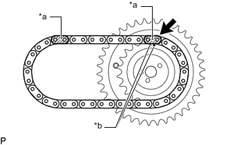
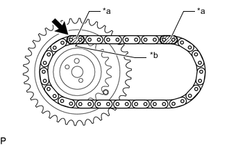
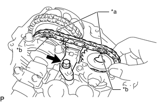
*a Mark Link (Yellow) *b Timing Mark Align the mark link (yellow) with the timing mark of the camshaft timing gear assembly.
-
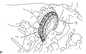
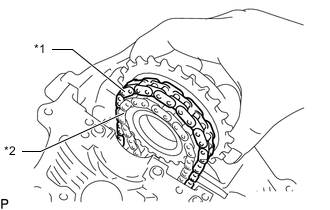
*1 Chain Sub-assembly *2 No. 2 Chain Sub-assembly Temporarily install the chain sub-assembly to the No. 2 chain sub-assembly.
-
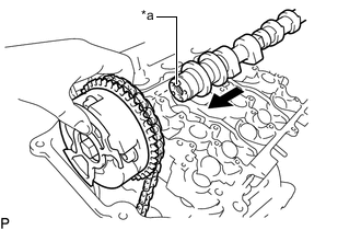
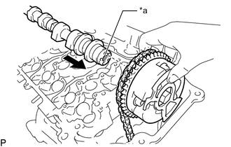
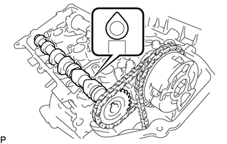
*a Knock Pin Align the knock pin hole of the camshaft timing gear assembly with the knock pin of the No. 3 camshaft sub-assembly and temporarily install the No. 3 camshaft sub-assembly to the camshaft timing gear assembly with the bolt.
-
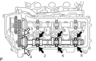
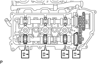
Set the No. 3 camshaft sub-assembly to the cylinder head LH as shown in the illustration.
-
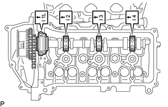
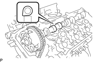
Check the numbers on the camshaft bearing caps and the installation direction before temporarily placing each cap.
-
Apply a light coat of engine oil to the threads and under the heads of the bolts.
-
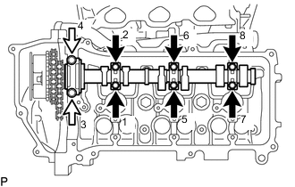

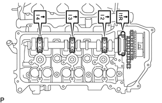
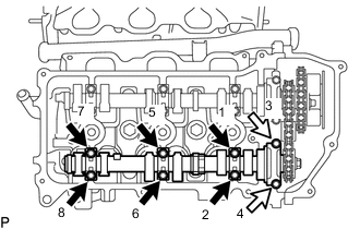
Bolt A 
Bolt B Install and uniformly tighten the 8 bolts in several steps in the sequence shown in the illustration.
- Torque:
- for bolt A
- 9.0 N*m { 92 kgf*cm, 80 in.*lbf }
- for bolt B
- 24 N*m { 245 kgf*cm, 18 ft.*lbf }
Standard Bolt Length Item Specified Condition Bolt A 39 mm (1.54 in.) Bolt B 50 mm (1.97 in.) -
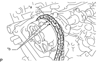
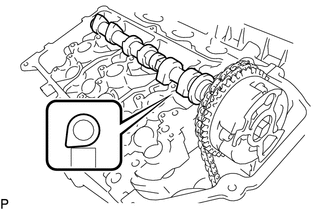
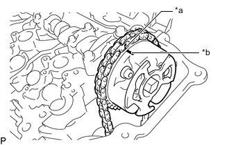
*a Paint Mark *b Timing Mark Set the paint mark of the chain sub-assembly between the timing marks of the camshaft timing gear assembly.
-
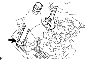
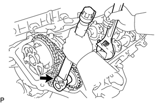
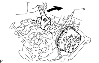
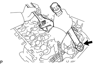
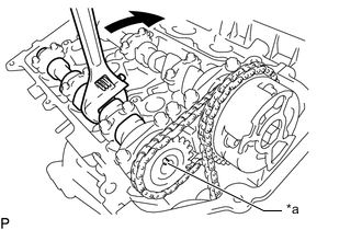
Hold the hexagonal portion of the No. 3 camshaft sub-assembly with a wrench and tighten the bolt.
- Torque:
- 100 N*m { 1020 kgf*cm, 74 ft.*lbf }
-
-
INSTALL NO. 3 CHAIN TENSIONER ASSEMBLY
-
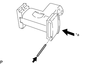
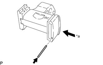
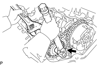
*a Push While pushing in the No. 3 chain tensioner assembly, insert a pin with a diameter of 1.0 mm (0.0394 in.) into the hole to fix the No. 3 chain tensioner assembly in place.
-
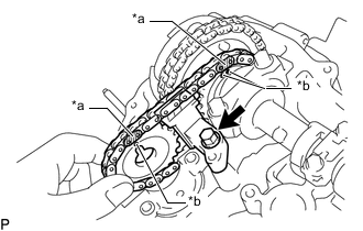
*a Mark Link (Yellow) *b Timing Mark Temporarily install the camshaft timing sprocket and No. 3 chain tensioner assembly with the bolt and align the mark links (yellow) with the timing marks of the camshaft timing gear assembly and camshaft timing sprocket.
-
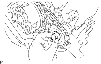
Tighten the bolt.
- Torque:
- 21 N*m { 214 kgf*cm, 15 ft.*lbf }
-
-
INSTALL NO. 4 CAMSHAFT SUB-ASSEMBLY
Note
As the thrust clearance of the No. 4 camshaft sub-assembly is small, the No. 4 camshaft sub-assembly must be kept level while it is being installed. If the No. 4 camshaft sub-assembly is not kept level, the portion of the cylinder head which receives the shaft thrust may crack or be damaged, causing the No. 4 camshaft sub-assembly to seize or break. To avoid this, make sure the following steps are carried out.
Tech Tips
Perform "Inspection After Repairs" after replacing the No. 4 camshaft sub-assembly.
-
Apply new engine oil to the thrust portions and journals of the No. 4 camshaft sub-assembly.
-
Align the knock pin hole of the camshaft timing sprocket with the knock pin of the No. 4 camshaft sub-assembly and temporarily install the No. 4 camshaft sub-assembly to the camshaft timing sprocket with the bolt.
-
Check the numbers on the camshaft bearing caps and the installation direction before temporarily placing each cap.
-
Apply a light coat of engine oil to the threads of the bolts.
-
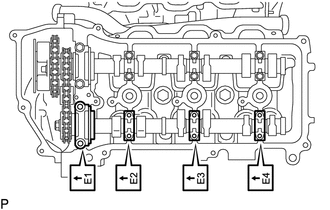
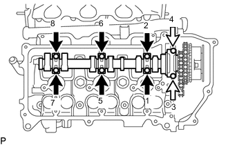
Bolt A Bolt B Install and uniformly tighten the 8 bearing cap bolts in several steps in the sequence shown in the illustration.
- Torque:
- for bolt A
- 9.0 N*m { 92 kgf*cm, 80 in.*lbf }
- for bolt B
- 24 N*m { 245 kgf*cm, 18 ft.*lbf }
Standard Bolt Length Item Specified Condition Bolt A 39 mm (1.54 in.) Bolt B 50 mm (1.97 in.) -
Hold the hexagonal portion of the No. 4 camshaft sub-assembly with a wrench and tighten the bolt.
- Torque:
- 100 N*m { 1020 kgf*cm, 74 ft.*lbf }
-
Remove the pin from the No. 3 chain tensioner assembly.
-

Release the chain tension between the camshaft timing gear assembly (for bank 1) and crankshaft timing sprocket by turning the crankshaft clockwise slightly.
-
-
INSTALL CAMSHAFT
Note
As the thrust clearance of the camshaft is small, the camshaft must be kept level while it is being installed. If the camshaft is not kept level, the portion of the cylinder head which receives the shaft thrust may crack or be damaged, causing the camshaft to seize or break. To avoid this, make sure the following steps are carried out.
Tech Tips
Perform "Inspection After Repairs" after replacing the camshaft or camshaft timing gear assembly.
-
Apply new engine oil to the thrust portions and journals of the camshaft.
-
*a Mark Link (Yellow) *b Timing Mark Align the mark link (yellow) with the timing mark of the camshaft timing gear assembly.
-
*1 Chain Sub-assembly *2 No. 2 Chain Sub-assembly Temporarily install the chain sub-assembly to the No. 2 chain sub-assembly.
-
*a Knock Pin Align the knock pin hole of the camshaft timing gear assembly with the knock pin of the camshaft and temporarily install the camshaft timing gear assembly to the camshaft with the bolt.
-
Set the camshaft to the cylinder head sub-assembly as shown in the illustration.
-
Check the numbers on the camshaft bearing caps and the installation direction before temporarily placing each cap.
-
Apply a light coat of engine oil to the threads and under the heads of the bolts.
-
Bolt A Bolt B Install and uniformly tighten the 8 bolts in several steps in the sequence shown in the illustration.
- Torque:
- for bolt A
- 9.0 N*m { 92 kgf*cm, 80 in.*lbf }
- for bolt B
- 24 N*m { 245 kgf*cm, 18 ft.*lbf }
Standard Bolt Length Item Specified Condition Bolt A 39 mm (1.54 in.) Bolt B 50 mm (1.97 in.) -
*a Timing Mark Rotate the camshaft and align the timing mark of the camshaft timing gear assembly with the timing mark of the camshaft bearing cap.
-
*a Paint Mark *b Timing Mark Align the paint mark of the chain sub-assembly with the timing mark of the camshaft timing gear assembly.
-
Hold the hexagonal portion of the camshaft with a wrench and tighten the bolt.
- Torque:
- 100 N*m { 1020 kgf*cm, 74 ft.*lbf }
-
-
INSTALL NO. 2 CHAIN TENSIONER ASSEMBLY
-
*a Push While pushing in the No. 2 chain tensioner assembly, insert a pin with a diameter of 1.0 mm (0.0394 in.) into the hole to fix the No. 2 chain tensioner assembly in place.
-
*a Mark Link (Yellow) *b Timing Mark Temporarily install the camshaft timing sprocket and No. 2 chain tensioner assembly with the bolt and align the mark links (yellow) with the timing marks of the camshaft timing gear assembly and camshaft timing sprocket.
-
Tighten the bolt.
- Torque:
- 21 N*m { 214 kgf*cm, 15 ft.*lbf }
-
-
INSTALL NO. 2 CAMSHAFT
Note
As the thrust clearance of the No. 2 camshaft is small, the No. 2 camshaft must be kept level while it is being installed. If the No. 2 camshaft is not kept level, the portion of the cylinder head which receives the shaft thrust may crack or be damaged, causing the No. 2 camshaft to seize or break. To avoid this, make sure the following steps are carried out.
-
Apply new engine oil to the thrust portions and journals of the No. 2 camshaft.
-
Set the No. 2 camshaft to the cylinder head sub-assembly as shown in the illustration.
-
Check the numbers on the camshaft bearing caps and the installation direction before temporarily placing each cap.
-
Apply a light coat of engine oil to the threads and under the bolts.
-
Bolt A Bolt B Install and uniformly tighten the 8 bolts in several steps in the sequence shown in the illustration.
- Torque:
- for bolt A
- 9.0 N*m { 92 kgf*cm, 80 in.*lbf }
- for bolt B
- 24 N*m { 245 kgf*cm, 18 ft.*lbf }
Standard Bolt Length Item Specified Condition Bolt A 39 mm (1.54 in.) Bolt B 50 mm (1.97 in.) -
*a Knock Pin Rotate the No. 2 camshaft and align the knock pin hole of the camshaft timing gear assembly with the knock pin of the No. 2 camshaft.
-
Hold the hexagonal portion of the No. 2 camshaft with a wrench and install the bolt.
- Torque:
- 100 N*m { 1020 kgf*cm, 74 ft.*lbf }
-
Remove the pin from the No. 2 chain tensioner assembly.
-
-
INSTALL NO. 1 CHAIN TENSIONER ASSEMBLY
-
Install the No. 1 chain tensioner assembly.
-
Remove the bar from the No. 1 chain tensioner assembly.
-
-
INSTALL TIMING CHAIN COVER PLATE
-
Install a new gasket and the timing chain cover plate with the 4 bolts.
- Torque:
- 9.1 N*m { 93 kgf*cm, 81 in.*lbf }
-
-
SET NO. 1 CYLINDER TO TDC/COMPRESSION
-
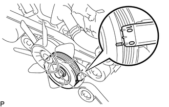
Turn the crankshaft pulley 2 complete revolutions slowly, and align the notch with the "0" timing mark of the timing chain cover sub-assembly.
-
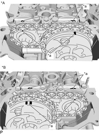
*A for Bank 1 *B for Bank 2 *a Timing Mark Check that the timing marks of the camshaft timing gears are aligned with the timing marks of the bearing caps as shown in the illustration.
-
-
INSPECT VALVE CLEARANCE
-
ADJUST VALVE CLEARANCE
-
INSTALL CYLINDER HEAD COVER SUB-ASSEMBLY LH
-
INSTALL CYLINDER HEAD COVER SUB-ASSEMBLY
-
INSTALL IGNITION COIL ASSEMBLY
-
INSTALL NO. 1 FUEL PIPE SUB-ASSEMBLY AND NO. 2 FUEL PIPE SUB-ASSEMBLY
-
INSTALL INTAKE AIR SURGE TANK
-
INSTALL FAN SHROUD
-
INSPECT IGNITION TIMING