CAMSHAFT REMOVAL
CAUTION / NOTICE / HINT
The necessary procedures (adjustment, calibration, initialization or registration) that must be performed after parts are removed, installed, or replaced during the camshaft removal/installation are shown below.
| Replacement Part or Procedure | Necessary Procedures | Effects/Inoperative when not Performed | Link |
|---|---|---|---|
|
Inspection after repair | Poor idle, engine start etc. |
CAUTION:
To prevent burns, do not touch the engine, exhaust manifold or other high temperature components while the engine is hot.
PROCEDURE
-
REMOVE FAN SHROUD
-
REMOVE INTAKE AIR SURGE TANK
-
REMOVE NO. 1 FUEL PIPE SUB-ASSEMBLY AND NO. 2 FUEL PIPE SUB-ASSEMBLY
-
REMOVE IGNITION COIL ASSEMBLY
-
REMOVE CYLINDER HEAD COVER SUB-ASSEMBLY
-
REMOVE CYLINDER HEAD COVER SUB-ASSEMBLY LH
-
SET NO. 1 CYLINDER TO TDC/COMPRESSION
-
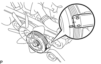
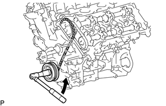
Turn the crankshaft pulley, and align the notch with timing mark 0 of the timing chain cover sub-assembly.
-
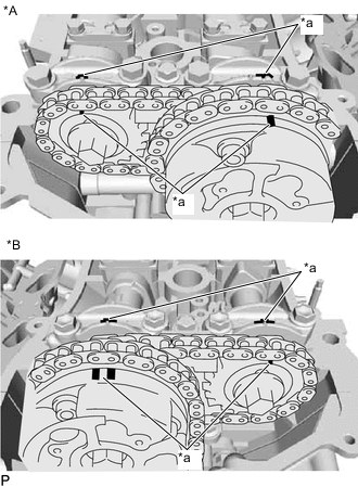
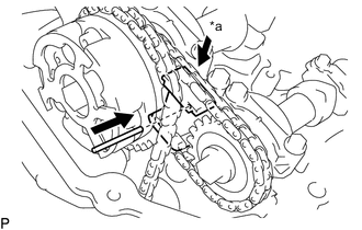
*A for Bank 1 *B for Bank 2 *a Timing Mark Check that the timing marks of the camshaft timing gears are aligned with the timing marks of the bearing cap as shown in the illustration.
If the timing marks are not aligned, turn the crankshaft 1 complete revolution (360°) and align the timing marks as described above.
-
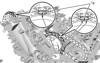
*a Paint Mark *b Timing Mark Place paint marks on the No. 1 chain sub-assembly links that correspond with the timing marks of the camshaft timing gears.
-
-
REMOVE TIMING CHAIN COVER PLATE
-
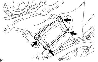
Remove the 4 bolts, timing chain cover plate and gasket.
-
-
REMOVE NO. 1 CHAIN TENSIONER ASSEMBLY
-
REMOVE NO. 2 CAMSHAFT
Note
As the thrust clearance of the No. 2 camshaft is small, the camshaft must be kept level while it is being removed. If the No. 2 camshaft is not kept level, the portion of the cylinder head which receives the shaft thrust may crack or be damaged, causing the No. 2 camshaft to seize or break. To avoid this, make sure the following steps are carried out.
-
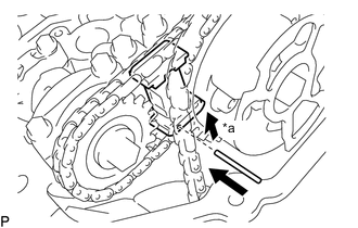
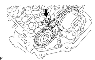
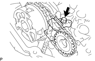
*a Raise While raising the No. 2 chain tensioner assembly, insert a pin with a diameter of 1.0 mm (0.0394 in.) into the hole to fix the No. 2 chain tensioner assembly in place.
-
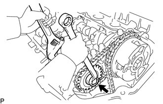
Hold the hexagonal portion of the No. 2 camshaft with a wrench and remove the bolt.
Note
Do not damage the surrounding parts.
-
Separate the camshaft timing sprocket from the No. 2 camshaft.
-
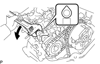
Rotate the No. 2 camshaft counterclockwise and set it as shown in the illustration.
-
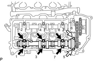
Uniformly loosen the 8 bolts in several steps in the sequence shown in the illustration and remove the bolts.
-
Remove the 4 camshaft bearing caps and No. 2 camshaft.
-
-
REMOVE NO. 2 CHAIN TENSIONER ASSEMBLY
-
Remove the bolt, No. 2 chain tensioner assembly and camshaft timing sprocket.
-
-
REMOVE CAMSHAFT
Note
As the thrust clearance of the camshaft is small, the camshaft must be kept level while it is being removed. If the camshaft is not kept level, the portion of the cylinder head which receives the shaft thrust may crack or be damaged, causing the camshaft to seize or break. To avoid this, make sure the following steps are carried out.
-
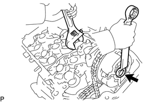
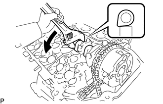
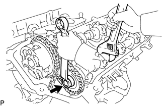
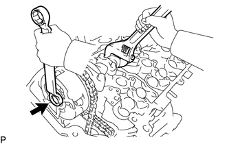
Hold the hexagonal portion of the camshaft with a wrench and loosen the bolt.
Note
-
Do not damage the surrounding parts.
-
Do not disassemble the camshaft timing gear assembly.
-
-
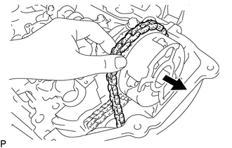

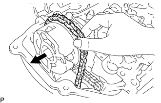
Slide Slide the camshaft timing gear assembly and separate the chain sub-assembly from the camshaft timing gear assembly.
-
Rotate the camshaft counterclockwise and set it as shown in the illustration.
-
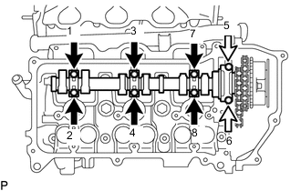
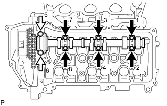
Uniformly loosen the 8 bolts in several steps in the sequence shown in the illustration and remove the bolts.
-
Remove the 4 camshaft bearing caps.
-
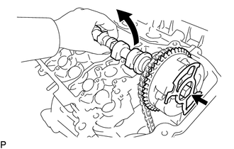
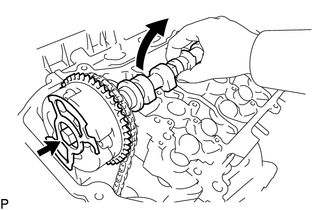
Remove the bolt with the camshaft lifted up, and then remove the camshaft and camshaft timing gear assembly together with the No. 2 chain sub-assembly.
-
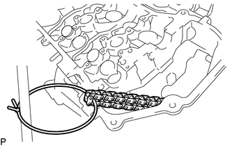
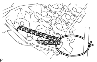
Tie the chain sub-assembly with a string as shown in the illustration.
Note
Be careful not to drop anything inside the timing chain cover sub-assembly.
-
-
REMOVE NO. 4 CAMSHAFT SUB-ASSEMBLY
Note
As the thrust clearance of the No. 4 camshaft sub-assembly is small, the No. 4 camshaft sub-assembly must be kept level while it is being removed. If the No. 4 camshaft sub-assembly is not kept level, the portion of the cylinder head which receives the shaft thrust may crack or be damaged, causing the No. 4 camshaft sub-assembly to seize or break. To avoid this, make sure the following steps are carried out.
-
*a Push While pushing down the No. 3 chain tensioner assembly, insert a pin with a diameter of 1.0 mm (0.0394 in.) into the hole to fix the No. 3 chain tensioner assembly in place.
-
Hold the hexagonal portion of the No. 4 camshaft sub-assembly with a wrench and remove the bolt.
Note
Do not damage the surrounding parts.
-
Separate the camshaft timing sprocket from the No. 4 camshaft sub-assembly.
-
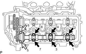
Uniformly loosen the 8 bolts in several steps in the sequence shown in the illustration and remove the bolts.
-
Remove the 4 camshaft bearing caps and No. 4 camshaft sub-assembly.
-
-
REMOVE NO. 3 CHAIN TENSIONER ASSEMBLY
-
Remove the bolt, No. 3 chain tensioner assembly and camshaft timing sprocket.
-
-
REMOVE NO. 3 CAMSHAFT SUB-ASSEMBLY
Note
As the thrust clearance of the No. 3 camshaft sub-assembly is small, the No. 3 camshaft sub-assembly must be kept level while it is being removed. If the No. 3 camshaft sub-assembly is not kept level, the portion of the cylinder head which receives the shaft thrust may crack or be damaged, causing the No. 3 camshaft sub-assembly to seize or break. To avoid this, make sure the following steps are carried out.
-
Release the chain tension between the camshaft timing gear assembly (for bank 2) and crankshaft timing sprocket by turning the crankshaft counterclockwise slightly.
-
Hold the hexagonal portion of the No. 3 camshaft sub-assembly with a wrench and loosen the bolt.
Note
-
Do not damage the surrounding parts.
-
Do not disassemble the camshaft timing gear assembly.
-
-
Slide Slide the camshaft timing gear assembly and separate the chain sub-assembly from the camshaft timing gear assembly.
-
Uniformly loosen the 8 bolts in several steps in the sequence shown in the illustration and remove the bolts.
-
Remove the 4 camshaft bearing caps.
-
Remove the bolt with the No. 3 camshaft sub-assembly lifted up, and then remove the No. 3 camshaft sub-assembly and camshaft timing gear assembly together with the No. 2 chain sub-assembly.
-
Tie the chain sub-assembly with a string as shown in the illustration.
Note
Be careful not to drop anything inside the timing chain cover sub-assembly.
-
-
INSPECT CAMSHAFT TIMING GEAR ASSEMBLY