| DTC Code | DTC Name |
|---|---|
| P1613 | Secondary Air Injection Driver Malfunction |
DESCRIPTION
Refer to DTC P0412.
| DTC No. | Detection Item | DTC Detection Condition | Trouble Area | MIL | Memory |
|---|---|---|---|---|---|
| P1613 | Secondary Air Injection Driver Malfunction | Condition 1: Either of following conditions (1) or (2) met (1) All of following conditions met (1 trip detection logic):
(2) Both of following conditions met (1 trip detection logic):
Condition 2:
Condition 3:
|
Condition 1:
Condition 2:
Condition 3:
|
Comes on | DTC stored |
MONITOR DESCRIPTION
This DTC indicates an open or short circuit in the secondary air injection system circuit or a malfunction in the air injection control driver itself. The air injection control driver performs diagnosis of the air pump, air switching valve and itself, and sends the results of this diagnosis to the ECM as a duty signal. When the ECM receives a signal indicating a malfunction in the air pump, air switching valve or air injection control driver, it immediately illuminates the MIL and stores a DTC.
MONITOR STRATEGY
| Required Sensors/Components (Main) | Air injection control driver |
| Frequency of Operation | Once per drive cycle |
CONFIRMATION DRIVING PATTERN
-
This Secondary Air Injection Check only allows technicians to operate the secondary air injection system for a maximum of 5 seconds.
Furthermore, the check can only be performed up to 4 times per trip. If the test is repeated, intervals of at least 30 seconds are required between checks.
While secondary air injection system operation using the GTS is prohibited, the GTS display indicates the prohibition (WAIT or ERROR).
If ERROR is displayed on the GTS during the test, stop the engine for 10 minutes, and then try again.
-
Performing the Secondary Air Injection Check repeatedly may cause damage to the secondary air injection system. If necessary, leave an interval of several minutes between System Check operations to prevent the system from overheating.
-
When performing the Secondary Air Injection Check operation after the battery cable has been reconnected, wait for 7 minutes with the ignition switch turned to ON or the engine running.
-
Turn the ignition switch off when the Secondary Air Injection Check operation finishes.
-
Start the engine and warm it up.
-
Turn the ignition switch off.
-
Connect the GTS to the DLC3.
-
Turn the ignition switch to ON.
-
Turn the GTS on.
-
Clear DTCs (even if no DTCs are stored, perform the clear DTC operation).
-
Turn the ignition switch off and wait for at least 30 seconds.
-
Turn the ignition switch to ON and turn the GTS on.
-
Enter the following menus: Powertrain / Engine and ECT / Utility / Secondary Air Injection Check / Automatic Mode.
-
Start the engine after the GTS initialization is finished.
-
Perform the System Check operation by pressing ENTER (Next).
-
Perform the following to confirm the secondary air injection system pending codes: Press the ENTER (Exit).
-
Check for pending DTCs.
OK No pending DTC is output. -
After the "Secondary Air Injection Check" is completed, check for All Readiness by entering the following menus: Powertrain / Engine and ECT / Utility / All Readiness.
-
Input the DTC: P1613.
-
Check the DTC judgment result.
GTS Display Description NORMAL
-
DTC judgment completed
-
System normal
ABNORMAL
-
DTC judgment completed
-
System abnormal
INCOMPLETE
-
DTC judgment not completed
-
Perform driving pattern after confirming DTC enabling conditions
N/A
-
Unable to perform DTC judgment
-
Number of DTCs which do not fulfill DTC preconditions has reached ECU memory limit
Tip:
-
If the judgment result shows NORMAL, the system is normal.
-
If the judgment result shows ABNORMAL, the system has a malfunction.
-
-
Turn the ignition switch off.
CAUTION / NOTICE / HINT
Inspect the fuses for circuits related to this system before performing the following inspection procedure.
Read freeze frame data using the GTS. Freeze frame data records the engine condition when malfunctions are detected. When troubleshooting, freeze frame data can help determine if the vehicle was moving or stationary, if the engine was warmed up or not, if the air-fuel ratio was lean or rich, and other data from the time the malfunction occurred.
PROCEDURE
- Click here
CHECK TERMINAL VOLTAGE (POWER SOURCE OF AIR INJECTION CONTROL DRIVER)
-
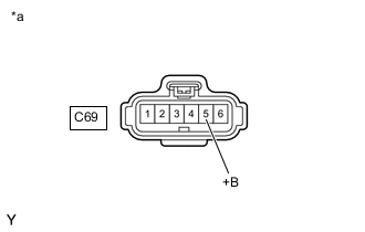
*a Front view of wire harness connector
(to Air Injection Control Driver)
Disconnect the air injection control driver connector.
-
Turn the ignition switch to ON.
-
Measure the voltage according to the value(s) in the table below.
Standard Voltage Tester Connection Switch Condition Specified Condition C69-5 (+B) - Body ground Ignition switch ON 11 to 14 V Result Proceed to OK NG
- OKClick here
- NG
REPAIR OR REPLACE HARNESS OR CONNECTOR
-
- Click here
CHECK HARNESS AND CONNECTOR (AIR INJECTION CONTROL DRIVER - ECM, BODY GROUND)
-
Disconnect the ECM connector.
-
Disconnect the air injection control driver connector.
-
Measure the resistance according to the value(s) in the table below.
Standard Resistance Tester Connection Condition Specified Condition G46-6 (AIRP) - C69-4 (SIP) Always Below 1 Ω G46-5 (AIRV) - C69-3 (SIV) Always Below 1 Ω G45-20 (AIDI) - C69-2 (DI) Always Below 1 Ω C52-3 (E1) - Body ground Always Below 1 Ω G46-6 (AIRP) or C69-4 (SIP) - Body ground Always 10 kΩ or higher G46-5 (AIRV) or C69-3 (SIV) - Body ground Always 10 kΩ or higher G45-20 (AIDI) or C69-2 (DI) - Body ground Always 10 kΩ or higher Result Proceed to OK NG
- OKClick here
- NG
REPAIR OR REPLACE HARNESS OR CONNECTOR
-
- Click here
INSPECT AIR INJECTION CONTROL DRIVER (DI TERMINAL VOLTAGE)
-
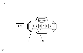
*a Front view of wire harness connector
(to Air Injection Control Driver)
Disconnect the air injection control driver connector.
-
Turn the ignition switch to ON.
-
Measure the voltage according to the value(s) in the table below.
Standard Voltage Tester Connection Switch Condition Specified Condition C69-2 (DI) - C69-1 (E) Ignition switch ON 11 to 14 V Result Proceed to OK NG
- OKClick here
- NG
REPLACE ECMClick here
-
- Click here
PERFORM ACTIVE TEST USING GTS
-
Disconnect the air injection control driver connector.
-
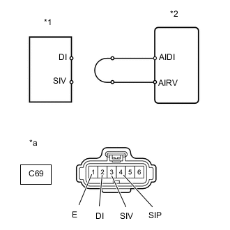
*1 Air Injection Control Driver *2 ECM *a Front view of wire harness connector
(to Air Injection Control Driver)
Connect terminals DI and SIV of the wire harness connector for the air injection control driver.
-
Connect the GTS to the DLC3.
-
Turn the ignition switch to ON.
-
Turn the GTS on.
-
Enter the following menus: Powertrain / Engine and ECT / Utility / Secondary Air Injection Check / Manual Mode / AIR PUMP: ON, ASV: OPEN.
- Powertrain > Engine > Utility
Tester Display Secondary Air Injection Check -
-
-
-
Tip:When Manual Mode is selected, the GTS initialization (atmospheric pressure measurement) is performed automatically. The initialization takes 10 seconds. After the initialization, AIR PUMP and ASV operation can be selected.
- Powertrain > Engine > Utility
-
Start the engine.
-
Perform the secondary air injection system intrusive operation while the engine is idling.
-
Measure the voltage between the SIV and E terminals of the ECM connector when the secondary air injection system is on and off.
-
Turn the ignition switch off.
Note:
-
Do not perform the System Check operation repetitively as it may cause the damage in the system. If necessary, leave an interval of several minutes between System Check operations.
-
When performing the Secondary Air Injection Check operation after the battery cable has been reconnected, wait for 7 minutes with the ignition switch ON or the engine running.
-
Turn the ignition switch off when the Secondary Air Injection Check operation finishes.
Standard Voltage Tester Connection Condition Specified Condition C69-3 (SIV) - C69-1 (E) AIR PUMP: ON, ASV: OPEN 0.5 to 2 V AIR PUMP: OFF, ASV: CLOSE 11 to 14 V -
-
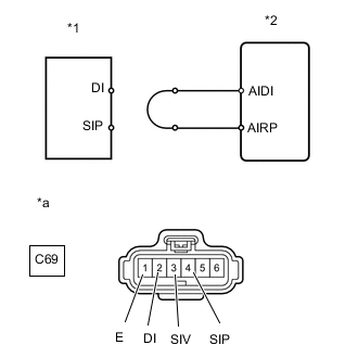
*1 Air Injection Control Driver *2 ECM *a Front view of wire harness connector
(to Air Injection Control Driver)
Connect terminals DI and SIP of the wire harness connector for the air injection control driver.
-
Connect the GTS to the DLC3.
-
Turn the ignition switch to ON.
-
Turn the GTS on.
-
Enter the following menus: Powertrain / Engine and ECT / Utility / Secondary Air Injection Check / Manual Mode / AIR PUMP: ON, ASV: OPEN.
- Powertrain > Engine > Utility
Tester Display Secondary Air Injection Check -
-
-
-
Tip:When Manual Mode is selected, the GTS initialization (atmospheric pressure measurement) is performed automatically. The initialization takes 10 seconds. After the initialization, AIR PUMP and ASV operation can be selected.
- Powertrain > Engine > Utility
-
Start the engine.
-
Perform the secondary air injection system intrusive operation while the engine is idling.
-
Measure the voltage between the SIP and E terminals of the ECM connector when the secondary air injection system is on and off.
-
Turn the ignition switch off.
Note:
-
Do not perform the System Check operation repetitively as it may cause the damage in the system. If necessary, leave an interval of several minutes between System Check operations.
-
When performing the Secondary Air Injection Check operation after the battery cable has been reconnected, wait for 7 minutes with the ignition switch ON or the engine running.
-
Turn the ignition switch off when the Secondary Air Injection Check operation finishes.
Standard Voltage Tester Connection Condition Specified Condition C69-4 (SIP) - C69-1 (E) AIR PUMP: ON, ASV: OPEN 0.5 to 2 V AIR PUMP: OFF, ASV: CLOSE 11 to 14 V Result Proceed to OK NG -
- OKClick here
- NG
REPLACE ECMClick here
-
- Click here
REPLACE AIR INJECTION CONTROL DRIVER
-
Replace the air injection control driver.
Result Proceed to NEXT
- NEXTClick here
-
- Click here
CHECK WHETHER DTC OUTPUT RECURS (SYSTEM CHECK AUTOMATIC MODE)
-
Start the engine and warm it up.
-
Turn the ignition switch off.
-
Connect the GTS to the DLC3.
-
Turn the ignition switch to ON.
-
Turn the GTS on.
-
Clear DTCs (even if no DTCs are stored, perform the clear DTC operation).
- Powertrain > Engine > Clear DTCs
-
-
-
Turn the ignition switch off and wait for at least 30 seconds.
-
Turn the ignition switch to ON and turn the GTS on.
-
Enter the following menus: Powertrain / Engine and ECT / Utility / Secondary Air Injection Check / Automatic Mode.
- Powertrain > Engine > Utility
Tester Display Secondary Air Injection Check -
-
-
-
- Powertrain > Engine > Utility
-
Start the engine after the GTS initialization is finished.
-
Perform the System Check operation by pressing ENTER (Next).
-
After operating the secondary air injection system, press the Exit button to confirm the secondary air injection system pending codes.
-
Check Pending DTCs.
OK No pending DTC output. -
Turn the ignition switch off.
Note:
-
When performing the Secondary Air Injection Check operation after the battery cable has been reconnected, wait for 7 minutes with the ignition switch turned to ON or the engine running.
-
Turn the ignition switch off when the Secondary Air Injection Check operation finishes.
Result Proceed to OK NG -
- OK
END
- NG
REPLACE ECMClick here
-