| DTC Code | DTC Name |
|---|---|
| Pattern Select Switch Eco Mode Circuit |
DESCRIPTION
Operating the ECO mode switch illuminates the ECO indicator light in the combination meter. This displays the ECO mode condition.
PROCEDURE
- Click here
READ VALUE USING GTS (ECO MODE SWITCH)
-
Connect the GTS to the DLC3.
-
Turn the ignition switch to ON.
-
Turn the GTS on.
-
Enter the following menus: Powertrain / Engine and ECT / Data List
-
According to the display on the GTS, read the Data List.
- Powertrain > Engine > Data List
Tester Display Measurement Item Range Normal Condition Diagnostic Note ECO Switch ECO mode switch status ON or OFF
-
ON: ECO MODE switch being pressed and held
-
OFF: ECO MODE switch not pressed
- -
-
-
- Powertrain > Engine > Data List
Tester Display ECO Switch -
-
-
-
Result Result Proceed to Data display is within Normal Condition range A Data display is not within Normal Condition range B - Powertrain > Engine > Data List
- A
PROCEED TO NEXT SUSPECTED AREA SHOWN IN PROBLEM SYMPTOMS TABLEClick here
- BClick here
-
- Click here
CHECK HARNESS AND CONNECTOR (ECO MODE SWITCH - BODY GROUND)
-
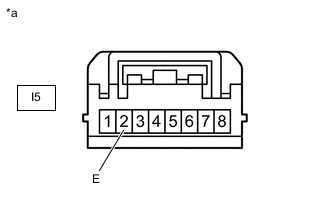
*a Front view of wire harness connector
(to ECO MODE Switch)
Disconnect the ECO MODE switch connector.
-
Measure the resistance according to the value(s) in the table below.
Standard Resistance Tester Connection Condition Specified Condition I5-2 (E) - Body ground Always Below 1 Ω Result Proceed to OK NG
- OKClick here
- NG
REPAIR OR REPLACE HARNESS OR CONNECTOR
-
- Click here
CHECK HARNESS AND CONNECTOR (ECO MODE SWITCH - ECM)
-
Disconnect the ECO MODE switch connector.
-
Disconnect the ECM connector.
-
Measure the resistance according to the value(s) in the table below.
Standard Resistance Tester Connection Condition Specified Condition I5-4 (ECU) - G46-13 (ECMS) Always Below 1 Ω I5-4 (ECU) or G46-13 (ECMS) - Body ground Always 10 kΩ or higher Result Proceed to OK NG
- OKClick here
- NG
REPAIR OR REPLACE HARNESS OR CONNECTOR
-
- Click here
INSPECT ECO MODE SWITCH
-
Inspect the ECO MODE switch.
Result Proceed to OK NG
- OK
PROCEED TO NEXT SUSPECTED AREA SHOWN IN PROBLEM SYMPTOMS TABLEClick here
- NG
REPLACE ECO MODE SWITCH (COMBINATION SWITCH ASSEMBLY)Click here
-