FUEL SYSTEM SYSTEM DIAGRAM

-
FUEL FLOW DIAGRAM
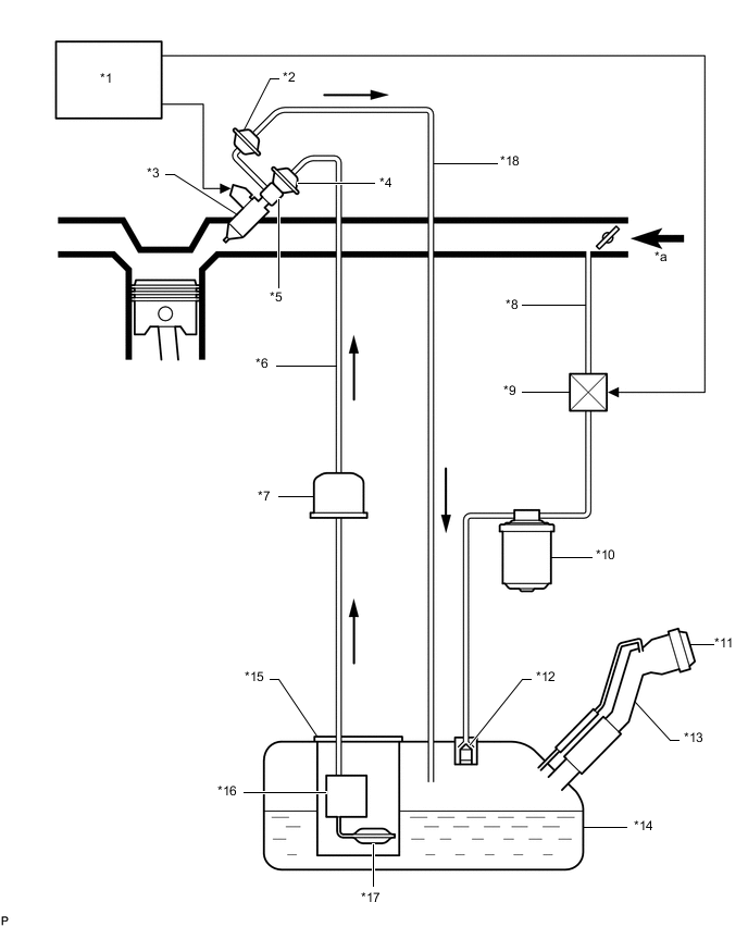
*1 ECM *2 Fuel Pressure Regulator Assembly *3 Fuel Injector Assembly *4 Fuel Pressure Pulsation Damper Assembly *5 Fuel Delivery Pipe Sub-assembly *6 Fuel Main Tube *7 Fuel Filter *8 Purge Line *9 Purge VSV *10 Canister *11 Fuel Tank Cap Assembly *12 Fuel Cutoff Valve *13 Fuel Tank Inlet Pipe Sub-assembly *14 Fuel Tank Assembly *15 Fuel Suction with Pump and Gauge Tube Assembly *16 Fuel Pump *17 Fuel Suction Filter *18 Fuel Return Tube *a Intake Air - - -
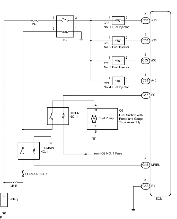
FUEL SYSTEM WIRING DIAGRAM
-
The fuel system is controlled by the ECM based on the intake air flow amount and signals from various sensors.
-