FUEL TANK(for Long Wheelbase) INSTALLATION

PROCEDURE
-
INSTALL FUEL TANK TO FILLER PIPE HOSE
-
for Type A:
-
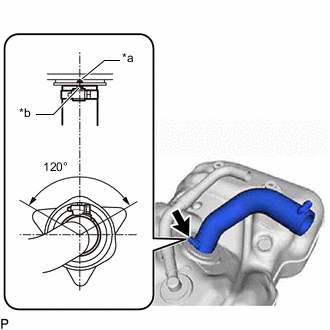
*a Protrusion *b Paint Mark Install the fuel tank to filler pipe hose to the fuel tank assembly, and tighten the clamp to secure the hose.
Tech Tips
Make sure the clamp is oriented as shown in the illustration.
-
Install the fuel hose to the fuel tank evaporation tube sub-assembly.
-
-
for Type B:
-
Install the fuel tank to filler pipe hose to the fuel tank assembly, and tighten the clamp to secure the hose.
-
Install the No. 3 fuel tube joint to the fuel tank cut off valve.
-
-
-
INSTALL FUEL TANK VENT TUBE ASSEMBLY
-
Apply a light coat of diesel fuel or grease to a new fuel tank vent tube gasket, and install it to the fuel tank sub-assembly.
-
Install the fuel tank vent tube assembly to the fuel tank sub-assembly.
Note
Be careful not to bend the arm of the fuel sender gauge assembly.
-
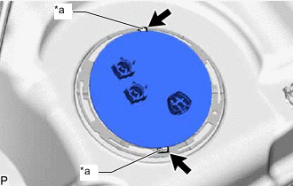
*a Protrusion 
Hole Align the protrusions of the fuel tank vent tube assembly with the holes in the fuel tank sub-assembly.
-
While pressing down on the fuel tank vent tube assembly, temporarily install the fuel pump gauge retainer.
-
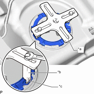
*a SST (Plate) *b SST (Claw) *c Insertion Point Set the 2 claws and plate of SST on the fuel pump gauge retainer.
- SST
- 09808-14030 ( 09808-01010, 09808-01030, 09808-01040 )
Tech Tips
Securely insert the ends of SST into the insertion points in the fuel pump gauge retainer.
-
While firmly pressing the claws of SST into the insertion points in the fuel pump gauge retainer, tighten the bolts of the claws.
-
Attach the handle of SST.
-
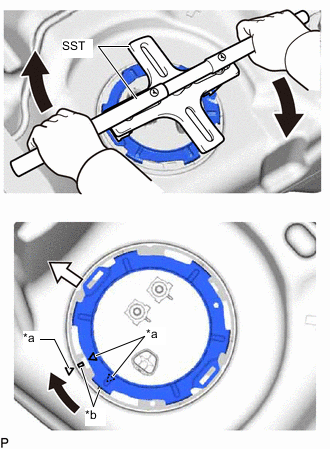
*a Alignment Mark *b Groove Turn 
Front of Vehicle Using SST, rotate the fuel pump gauge retainer so that the protrusions of the fuel pump gauge retainer are aligned with the grooves in the fuel tank sub-assembly to install the fuel tank vent tube assembly to the fuel tank sub-assembly.
Note
-
Do not use any tools other than SST, such as a screwdriver, etc.
-
Do not use excessive force when pressing down on SST, as the fuel pump gauge retainer will place excessive force on the fuel tank vent tube assembly and be difficult to remove, and parts may be damaged.
-
Be sure to keep the handle level when turning it, as SST may slip off the retainer if the handle is turned at an angle with excessive force.
-
Do not use an impact wrench or turn the handle with excessive force, as parts may be damaged.
-
If SST slips off the fuel pump gauge retainer, loosen the bolts and reattach SST to the fuel pump gauge retainer.
-
-
Insert the fuel tank main tube sub-assembly and fuel tank return tube into the plugs of the fuel tank vent tube assembly and fix them in place with the 2 tube joint clips.
Note
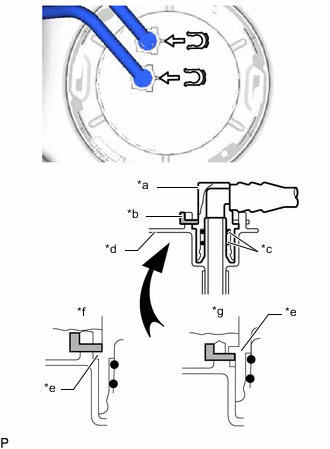
*a Fuel Tube Joint *b Tube Joint Clip *c O-Ring *d Fuel Tank Vent Tube Assembly *e Collar *f CORRECT *g INCORRECT
-
Check that there are no scratches or foreign objects on the connecting parts.
-
Check that the fuel tube joints are inserted securely.
-
Check that the tube joint clips are on the collars of the fuel tube joints.
-
After installing the tube joint clips, check that the fuel tube joints cannot be pulled off.
-
Be careful not to damage any clips.
If a clip is damaged, replace it.
-
-
-
INSTALL NO. 3 FUEL TUBE CLAMP
-
Attach the claw to install the No. 3 fuel tube clamp.
-
-
INSTALL FUEL TANK CUSHION
-
Install the 2 new fuel tank cushions to the fuel tank sub-assembly.
-
-
INSTALL NO. 1 FUEL TANK HEAT INSULATOR
-
Install the No. 1 fuel tank heat insulator with the 4 fuel tank bolts and nut.
- Torque:
- 6.0 N*m { 61 kgf*cm, 53 in.*lbf }
-
-
INSTALL FUEL TANK ASSEMBLY
CAUTION:
The fuel tank assembly is very heavy. Be sure to follow the procedure described in the repair manual, or the fuel tank assembly may fall off the engine lifter.
-
Set the fuel tank sub-assembly on an engine lifter and raise the fuel tank sub-assembly.
Note
Do not allow the fuel tank sub-assembly to contact the vehicle, especially the differential.
-
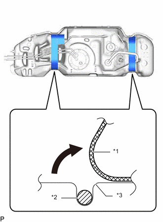
*1 Fuel Tank Cushion *2 Wire Harness *3 Fuel Tank Assembly Fold back approximately half of each fuel tank cushion so that the wire harness can be installed in the step below.
-
Attach the wire harness to the 6 clamps and connect the fuel sender gauge connector.
Note
Be careful not to cut the wire harness.
-
for Smart Cab:
Install the fuel tank protector with attach the 3 claws.
-
Install the 2 fuel tank bands with the 2 fuel tank band pins and 2 clips.
-
Install the 2 fuel tank bands with the 2 bolts.
- Torque:
- 45 N*m { 459 kgf*cm, 33 ft.*lbf }
-
-
CONNECT FUEL TANK TO FILLER PIPE HOSE
-
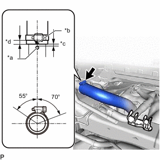
*a Protrusion *b Paint Mark (Yellow) *c 0 to 3 mm (0 to 0.118 in.) *d 2 to 7 mm (0.0787 to 0.276 in.) Connect the fuel tank to filler pipe hose to the fuel tank filler pipe sub-assembly, and tighten the clamp to secure the hose.
Tech Tips
Make sure the clamp is oriented as shown in the illustration.
-
-
CONNECT FUEL TANK BREATHER HOSE
-
for Type A:
-
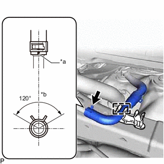
*a Paint Mark *b Top of Vehicle Connect the fuel tank breather hose to the fuel tank filler pipe sub-assembly, and slide the clamp to secure the hose.
Tech Tips
Make sure the clamp is oriented as shown in the illustration.
-
Connect the fuel hose to the fuel tank filler pipe sub-assembly.
-
Attach the 2 clamps to connect the fuel tank breather hose and fuel hose.
-
-
for Type B:
-
Connect the fuel tank breather hose to the fuel tank filler pipe sub-assembly, and slide the clamp to secure the hose.
Tech Tips
Make sure the clamp is oriented as shown in the illustration.
-
Attach the clamp to connect the fuel tank breather hose.
-
-
-
CONNECT FUEL TANK MAIN TUBE SUB-ASSEMBLY AND FUEL TANK RETURN TUBE
-
Connect the 2 fuel hoses to the fuel tank main tube sub-assembly and fuel tank return tube, and slide the 2 clamps to secure the hoses.
-
-
INSTALL NO. 1 FUEL TANK PROTECTOR
-
Install the fuel tank protector to the fuel tank sub-assembly with the 5 nuts.
- Torque:
- 13 N*m { 133 kgf*cm, 10 ft.*lbf }
-
-
INSTALL FUEL TANK CAP ASSEMBLY
-
CONNECT CABLE TO NEGATIVE BATTERY TERMINAL
Note
When disconnecting the cable, some systems need to be initialized after the cable is reconnected.
-
BLEED AIR FROM FUEL SYSTEM
-
INSPECT FOR FUEL LEAK